Manuals
/
Milnor
/
Laundry Appliance
/
Clothes Dryer
Milnor
KURSPK0025, KURSPK0026
manual
HURSPK0026/00186
Models:
KURSPK0025
KURSPK0026
1
19
30
30
Download
30 pages
44.63 Kb
16
17
18
19
20
21
22
23
Setting Limit Switches
Roller Plunger Switch Angle
Page 19
Image 19
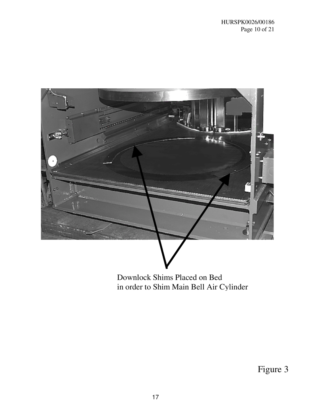
HURSPK0026/00186
Page 10 of 21
Downlock Shims Placed on Bed
in order to Shim Main Bell Air Cylinder
Figure 3
17
Page 18
Page 20
Page 19
Image 19
Page 18
Page 20
Contents
KURSPK0025 KURSPK0026
Please Read
Setting Limit Switches
Setting Switches
Right
Roller Plunger Switch Angle
Press Safety for Installation and Service
Page
Page
Instructions for 50 Kilo and 60 Kilo Press Shim RETRO-FIT
Page
Page
Page
Page
Example
Page
HURSPK0026/00186
Torque To Ft-lb
HURSPK0026/00186
One of the Four Main Bell Air Cylinder Bolts
Main Bell Air Cylinder Shims
HURSPK0026/00186
HURSPK0026/00186
Right-Hand Side Lock Shaft Bearing
Upper Cross-Member
HURSPK0026/00186
Old Setup of Dome Full-Up Contact Switch and Bracket
HURSPK0026/00186
HURSPK0026/00186 Page 20
Location of Downlock Shims Lock Ring Bolts
Top
Page
Image
Contents