Milnor KURSPK0026, KURSPK0025 manual Setting Switches, Where Lever or Plunger Should Stop

Models: KURSPK0025 KURSPK0026

1 30
Download 30 pages 44.63 Kb
Page 4
Image 4
Setting Switches

Setting Switches

B

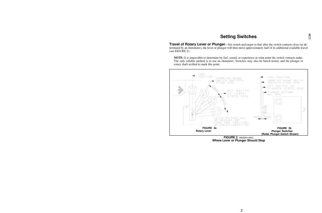
Travel of Rotary Lever or Plunger—Set switch and target so that after the switch contacts close (as de- termined by an ohmmeter), the lever or plunger will then move approximately half of its additional available travel (see FIGURE 2).

NOTE: It is impossible to determine by feel, sound, or experience at what point the switch contacts make. The only reliable method is to use an ohmmeter. Switches may also be bench-tested, and the plunger or rotary shaft scribed to mark this point.

FIGURE 2a

FIGURE 2b

Rotary Lever

Plunger Switches


(Roller Plunger Switch Shown)

FIGURE 2 (MSSM0116AE)

Where Lever or Plunger Should Stop

2

Page 4
Image 4
Milnor KURSPK0026, KURSPK0025 manual Setting Switches, Where Lever or Plunger Should Stop