4.To install a blade, place the blade on the spindle with the teeth pointing in the same direction as the arrow on the lower guard (Fig. 4). Release the lower guard lever.
Fig. 4
5.Place the blade flange on the spindle and hand tighten the bolt.
6.While holding in the spindle lock button, use the wrench to turn the bolt counter- clockwise and tighten.
Adjusting Depth
1.Remove battery pack.
2.To adjust the depth of the cut, hold the saw by the handle and loosen the depth adjusting lever by pushing it down toward the shoe (Fig. 5).
Fig. 5
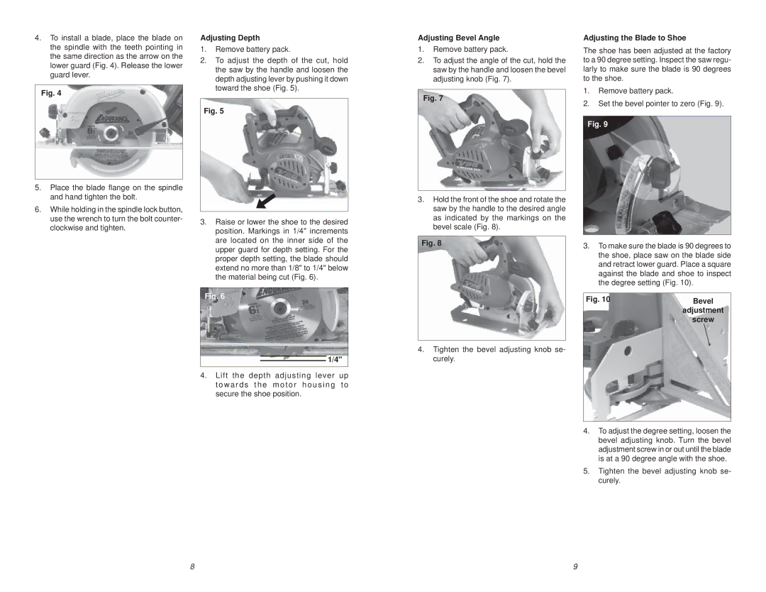
3.Raise or lower the shoe to the desired position. Markings in 1/4" increments are located on the inner side of the upper guard for depth setting. For the proper depth setting, the blade should extend no more than 1/8" to 1/4" below the material being cut (Fig. 6).
Fig. 6
1/4"
4.Lift the depth adjusting lever up towards the motor housing to
secure the shoe position.
Adjusting Bevel Angle
1.Remove battery pack.
2.To adjust the angle of the cut, hold the saw by the handle and loosen the bevel adjusting knob (Fig. 7).
Fig. 7
3.Hold the front of the shoe and rotate the saw by the handle to the desired angle as indicated by the markings on the bevel scale (Fig. 8).
Fig. 8
4.Tighten the bevel adjusting knob se- curely.
Adjusting the Blade to Shoe
The shoe has been adjusted at the factory to a 90 degree setting. Inspect the saw regu- larly to make sure the blade is 90 degrees to the shoe.
1.Remove battery pack.
2.Set the bevel pointer to zero (Fig. 9).
Fig. 9
3.To make sure the blade is 90 degrees to the shoe, place saw on the blade side and retract lower guard. Place a square against the blade and shoe to inspect the degree setting (Fig. 10).
Fig. 10 | Bevel |
| adjustment |
| screw |
4.To adjust the degree setting, loosen the bevel adjusting knob. Turn the bevel adjustment screw in or out until the blade is at a 90 degree angle with the shoe.
5.Tighten the bevel adjusting knob se- curely.
8 | 9 |