2. INDOOR UNIT INSTALLATION

2-1. ATTACHING THE INSTALLATION PLATE

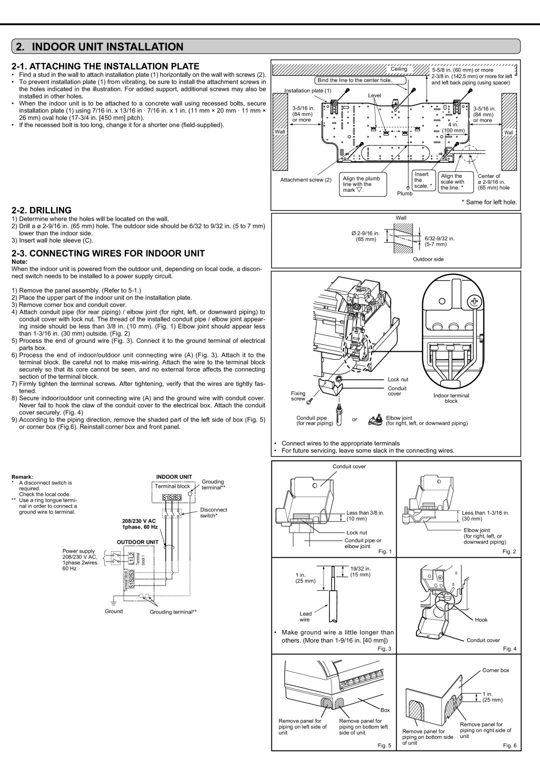
Find a stud in the wall to attach installation plate (1) horizontally on the wall with screws (2).

To prevent installation plate (1) from vibrating, be sure to install the attachment screws in the holes indicated in the illustration. For added support, additional screws may also be installed in other holes.

When the indoor unit is to be attached to a concrete wall using recessed bolts, secure installation plate (1) using 7/16 in. x 13/16 in · 7/16 in. x 1 in. (11 mm × 20 mm · 11 mm × 26 mm) oval hole (17-3/4 in. [450 mm] pitch).

‡ ,IWKHUHFHVVHGEROWLVWRRORQJFKDQJHLWIRUDVKRUWHURQH ¿HOGVXSSOLHG 

2-2. DRILLING

1)Determine where the holes will be located on the wall.

2)Drill a ø 2-9/16 in. (65 mm) hole. The outdoor side should be 6/32 to 9/32 in. (5 to 7 mm) lower than the indoor side.

3)Insert wall hole sleeve (C).

2-3. CONNECTING WIRES FOR INDOOR UNIT

Note:

When the indoor unit is powered from the outdoor unit, depending on local code, a discon- nect switch needs to be installed to a power supply circuit.

1)Remove the panel assembly. (Refer to 5-1.)

2)Place the upper part of the indoor unit on the installation plate.

3)Remove corner box and conduit cover.

4)Attach conduit pipe (for rear piping) / elbow joint (for right, left, or downward piping) to conduit cover with lock nut. The thread of the installed conduit pipe / elbow joint appear- ing inside should be less than 3/8 in. (10 mm). (Fig. 1) Elbow joint should appear less than 1-3/16 in. (30 mm) outside. (Fig. 2)

5)Process the end of ground wire (Fig. 3). Connect it to the ground terminal of electrical parts box.

6)Process the end of indoor/outdoor unit connecting wire (A) (Fig. 3). Attach it to the terminal block. Be careful not to make mis-wiring. Attach the wire to the terminal block securely so that its core cannot be seen, and no external force affects the connecting section of the terminal block.

7)Firmly tighten the terminal screws. After tightening, verify that the wires are tightly fas- tened.

8)Secure indoor/outdoor unit connecting wire (A) and the ground wire with conduit cover. Never fail to hook the claw of the conduit cover to the electrical box. Attach the conduit cover securely. (Fig. 4)

9)According to the piping direction, remove the shaded part of the left side of box (Fig. 5) or corner box (Fig.6). Reinstall corner box and front panel.

Ceiling

5-5/8 in. (60 mm) or more


Bind the line to the center hole.

2-3/8 in. (142.5 mm) or more for left

and left back piping (using spacer)


Installation plate (1)


Level


3-5/16 in.

3-5/16 in.


(84 mm)

(84 mm)


or more

or more


4 in.


Wall

(100 mm)

Wall

Attachment screw (2)

Align the plumb

Insert

Align the

Center of

the

scale with

ø 2-9/16 in.


line with the

scale. *


the line. *

(65 mm) hole


mark .

Plumb


* Same for left hole.


Wall

Ø 2-9/16 in.

6/32-9/32 in.

(65 mm)


(5-7 mm)


Outdoor side


Lock nut


Fixing


Conduit


cover

Indoor terminal

screw


block


Conduit pipe

or

Elbow joint


(for rear piping)


(for right, left, or downward piping)

Connect wires to the appropriate terminals

For future servicing, leave some slack in the connecting wires.

Conduit cover

Remark:

*A disconnect switch is required.

Check the local code.

**Use a ring tongue termi- nal in order to connect a ground wire to terminal.

Power supply 208/230 V AC, 1phase 2wires. 60 Hz

INDOOR UNIT

Grouding

Terminal block

terminal**

Disconnect switch*

208/230 V AC 1phase, 60 Hz

OUTDOOR UNIT

Terminal

block 1

Terminal block 2


Less than 3/8 in.

Less than 1-3/16 in.

(10 mm)

(30 mm)

Lock nut

Elbow joint

(for right, left, or

Conduit pipe or

downward piping)

elbow joint

Fig. 2

Fig. 1

19/32 in.

1 in. (15 mm)

(25 mm)

Ground

Grouding terminal**

Lead


wire

Hook

• Make ground wire a little longer than


others. (More than 1-9/16 in. [40 mm])


Conduit cover


Fig. 3


Fig. 4


Corner box


1 in.


(25 mm)


Box


Remove panel for

Remove panel for


Remove panel for

piping on left side of

piping on bottom left


Remove panel for

piping on right side of

unit

side of unit


piping on bottom side

unit


Fig. 5

of unit

Fig. 6


Page 4
Image 4
Mitsubishi Electronics MSZ-FD09/12NA Indoor Unit Installation, Attaching the Installation Plate, Drilling

MSZ-FD09/12NA specifications

Mitsubishi Electronics has been a leader in the HVAC industry for decades, and the MSZ-FD09/12NA is a testament to their commitment to innovation and efficiency. This wall-mounted indoor unit is part of Mitsubishi's compact and stylish FD Series, catering to both residential and commercial applications.

One of the standout features of the MSZ-FD09/12NA is its advanced energy efficiency. With a high seasonal energy efficiency ratio (SEER) rating, this model operates quietly while consuming minimal power, making it an environmentally friendly choice that can significantly reduce electricity bills. This level of efficiency is particularly beneficial for users looking to maintain a sustainable lifestyle.

The MSZ-FD09/12NA incorporates Mitsubishi’s INVERTER technology, allowing for continuous adjustments to the compressor speed. This results in more precise temperature control, maintaining comfort levels without the energy spikes commonly associated with traditional cooling and heating systems. This technology not only enhances comfort but also extends the lifespan of the unit through reduced wear and tear.

Enhanced air filtration is another important characteristic of the MSZ-FD09/12NA. The unit comes equipped with a multi-stage filtration system that includes a special anti-allergen filter. This feature is particularly beneficial for allergy sufferers, as it captures dust, pollen, and other airborne particles, ensuring cleaner air in the household or workspace.

In terms of design, the MSZ-FD09/12NA is sleek and unobtrusive, blending seamlessly with modern interiors. Its compact size doesn’t compromise its performance, making it an ideal choice for rooms with limited space. Furthermore, the unit operates quietly, with noise levels as low as 19 decibels, allowing for a peaceful environment free from disruptive sounds.

Control options for the MSZ-FD09/12NA are versatile. Users can utilize a wireless remote control for convenience or connect the unit to a centralized smart home system for enhanced functionality. This capability allows for temperature adjustments from anywhere in the home, offering significant flexibility for homeowners.

Overall, the Mitsubishi MSZ-FD09/12NA stands out in the crowded HVAC market for its combination of energy efficiency, advanced technologies, and user-friendly features. Whether it's for residential comfort or commercial applications, this unit promises consistent performance and reliability, ensuring that it meets the diverse needs of modern consumers.