Service Handbook
Page
Contents
Carefully read the labels affixed to the main unit
Safety precautions
Use a vacuum pump with a reverse flow check valve
Be especially careful when managing the tools
Do not use the existing refrigerant piping
Use liquid refrigerant to seal the system
Storage of Piping Material
Reason
Piping Machining
Reasons
When non-oxide brazing was used
Brazing
Items to be strictly observed
Vacuuming
Airtightness Test
R22 leakage detector
R410A-Pink
Charging of Refrigerant
Dryer
Cylinder color identification R407C-Gray
Outdoor unit PURY-P400·500YMF-C
Appearance of Components
P400 Type P500 Type
51C2 Module IPM Board
Controller Box
Noise filter Magnetic contactor 52C1 Capacitor C2, C3 52F
Puhy / Pury
Main board
INV board
CNE CNDC1
Fancon board
Board
Cnpow Cnfan CNFC2
SNB board Board
Earth
BC controller
Cntr
SW4 SW5 SW2 SW1
Relay 10 board Relay 4 board
SV8 SV7
ACC
LEV1 SVM1
CMB-P108, 1010, 1013, 1016V-FA
LEV3 SVM2
PS3
TH25
LEV3a
TH22
PURY-P400·500YMF-C
Electrical Wiring Diagram
SV7B SV7A SV7C SV8B SV8A SV8C
CMB-P108·1010V-FA
CMB-P1013·1016V-FA
Symbol
LEV3
CMB-P108V-FB
DB/WB
Standard Operation Data
Cooling operation
PURY-P400YMF-C PURY-P500YMF-C
Heating operation
SW3
Ture Power is on Defrosting end tempera
Function of Dip SW and Rotary SW
SWU
Model P71 P80 P100 P125 P140
SW2 setting
Indoor unit DIP SW1
P40 P50 P63
SW4
220V 240V
Function
Check points before test run
Before Test Run
Connected indoor units Can be connected without a RP
Insulation pipe
Check points for test run when mounting options
Local remote controller displays code No
Built-in optional parts
Portion
Check points for system structure
Not heat at heating
Example, 200m or less total length 500m at the farthest
Error stop, compressor trouble
CN40 on the Main board when the system is centralized
Turn on power source 12 hours before starting operations?
Warm or cold air is blowing out
Test Run Method
Test RUN
Switch function
Filter +
Controlled
Description of registration/deletion/retrieval
Attribute display of unit
Group registration of indoor unit
Registration procedure
No registration
Operation procedure
Press the switch for confirmation E
Switch G for the interlocked setting mode. See figure below
Deletion completed Case of group re
Press the switch for confirmation F twice continuously
Deletion of address not existing
Compressor capacity control
Control of Outdoor Unit 1- 1 PURY-P400·500 YMF-C
Initial processing
Control at staring
OFF
Bypass capacity control
SV6a
Stop
SV1
Defrosting control
Oil return control Electronic expansion valve Slev
Judgement and control of refrigerant amount
Control of liquid level detecting heater
Outdoor unit heat exchanger capacity control
Four-way valve
Heat exchanger TH9
Accumulator CS circuit
Control at initial starting
Start of initial operation mode Step
End of initial operation mode 5 minutes Example
Initial start control timing chart
Example Minutes
400 500 No Compressor Failure 48 % 65 %
Emergency response operating mode
Control of LEV
Control of BC Controller
Control of SVA, SVB and SVC
Control of SVM1 only FA type
Outdoor unit
Operation Flow Chart
Normal operations Trouble observed Stop
Normal operations
Operation No command
BC controller
Start
Indoor unit
Test run start Thermostat on
Cooling operation
Normal operations Test run Stop
Cooling operation Way valve OFF Indoor unit fan Operations
Normal operations Defrosting operations Stop Test run
Heating operation
Same as those in cooling operations
Dry operation
Thermostat on
Thermostat on Inlet temp ˚C
MC1
List of Major Component Functions
MC2
TH6
TH3
TH4
TH5
CH3
CH2
Resistance of Temperature Sensor
Symptom
Operating Characteristics and Refrigerant Amount
Adjustment and Judgement of Refrigerant Amount
Low temperature than overload Control system Temperature
Additional Refrigerant Charge Volume
Refrigerant Volume
PURY-P400YMF-C PURY-P500YMF-C
SC11 SC16
Refrigerant Volume Adjustment Mode Operation
Procedure
TH1
Adjustment starts
YES
Turn all of switches Readjust
SW1 OFF
18 kg 27 kg 31 kg
Pipe Length Or less 60 ~ 90 m
Judging Failure
Connector GND Black Vout White Vcc DC5V Red
Principal Parts
Pressure Sensor
SV3 SV4 SV5 SV6
Solenoid Valve SV1~8
SW1
LED
Solenoid Valves Block1
CV4b
Solenoid Valves Block
SV8 CV7b
CV5b
Check Valves Block1
CV6b
CV5b CV4b CV2b CV3b
Check Valves Block2
Check Valves Block2
LEV Valve Closing and Valve Opening Operations
Outdoor LEV
Intake temperature display, it can
Temperature sensed by Thermistor liquid pipe temperature
Temperature is considerably low
Compared to the remote control’s
Part a
10~50 Ω Tester
Intelligent Power Module IPM
Diode stack
Tester ⊕
NET transmission line break on the side of the room unit
Check method and handling
After checking , if these are factors
Check voltage between a and B
Power terminal block Voltage Verify the power
INV board----CNAC2, CNVCC1, CNL2
Phenomena
Unit is removed
Main board ----CNS1, CNVCC3
CNS1, CNVCC3
Case of M-NET remote controller
30V Check Procedure
No powering signal INV board
Checking method & countermeasure Case Melans is not used
Transmission line Wiring miss Door unit M-NET 17 ~ 30V?
Normal in case of 10V ~
Melans
CNR, CNAC2
Investigation of transmission wave shape/noise
Earthing
Forwiring
Method
Checking
Vidual Parts Failure Judgment Methods
Disconnected wires should Insulation resistance 2MΩ or more
If the problem is solved and you connect
Again, replace the compressor
CNFC1~CNFC2
TB1A~NF~TB1B~CNTR1~T01~CNTR
TB1B~CNPOW, CNFAN~CN04~CNMF
CNFAN~52F~CN05~CNMF
IPM
20~60Ω AC Current sensor Acct
A1-A2
Black Capacitor C2,C3 Board Red
Motor Compressor Red White Black
OK?
Troubleshooting the major components of the BC controller
Pressure sensor Pressure sensor troubleshooting flow
Start
HPS
Problem No abnormality
Temperature Sensor Thermistor troubleshooting flow
Temperature ˚C
Temperature sensor resistance graph
Resistance value Thermistor R o=15 k Ω Rt=15exp 273+t
LEV, Solenoid Valve Troubleshooting Flow
LEV
Output superheat BC controller
Subcool Solenoid Valve Troubleshooting Flow
Intermediate subcool BC controller liquid
Solenoid Valve
Normal Malfunction
SVM is turned on and off in accordance with operation mode
Disconnect the connector before measurement
SVM1
Service panel
BC Controller Disassembly Procedure
Control Box
Ler panel TH11 TH12 CN10 TH15, TH16 CN11
Thermistor Liquid and gas piping temperature detection
Be careful when removing heavy parts Procedure
100
LEV3 LEV1
101
LEV
Solenoid Valve Coil
102
103
CNRS2 CNRS3
Mechanical
CNAC2 TB1B
105
LEV3 SVM BC
106
SVM1 LEV3
LEV3 SVM SVA BC
107
LEV3 SVM
108
SVA SV3~8
Slev
109
2502 Drain pump
110
Once vacuum operation protection is
Indoor and outdoor units by oper
TB1A~NF~TB1B~CNTR1~F3~
111
T01~CNTR
VDC
112
TB1A~NF~TB1B, TB1B~DS~52C
MF1~CNFAN
113
114
TH8
115
TH HS
Thhs TH5
CNDR2-CNDR1
116
IPM-MC1
117
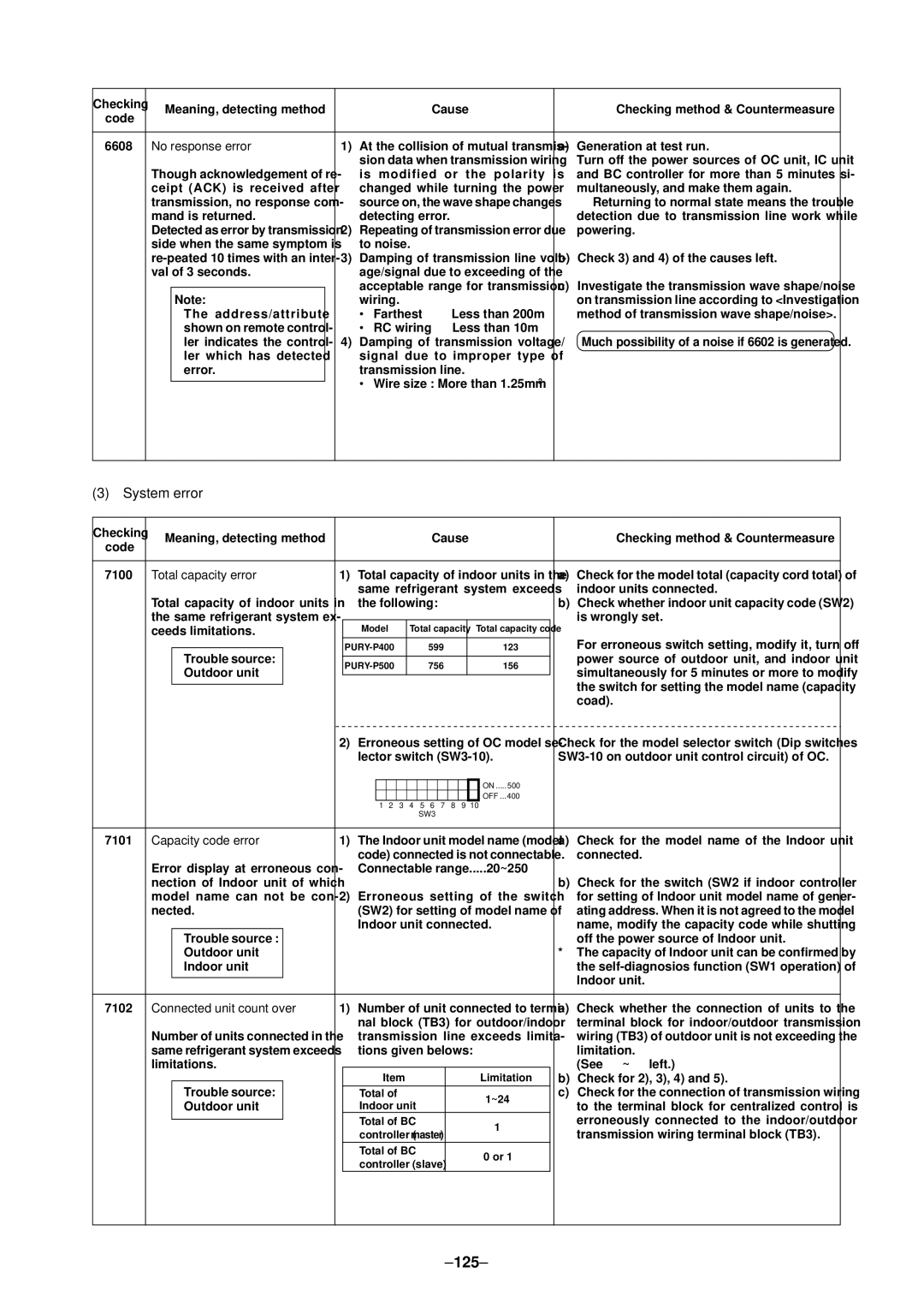
Communication/system
Error
On, the wave shape is changed and the error is detected
118
→ Noise if existed, check the noise
Checking method and processing Error
119
Transmission circuit bus-busy er
120
Communication trouble between Faulty generating controller
More, and make them again
Shut down OC unit power source,
Remote No reply Faulty transmission wiring at IC unit side
Generating Display Detecting
122
123
124
125
System error
126
Comp
How to read LED for service monitor
LED Monitor Display
127
TH2 TH3 TH4 TH5 TH6 TH7
128
LD1 LD2 LD3 LD4 LD5 LD6 LD7 LD8
Comp COMP1
129
130
LD1 LD2 LD3 LD4 LD5 LD6 LD7 LD8
131
132
IC16SC
133
134
135
136
137
IC24SH
138
IC24SC
139
140
141
Check that all indoor units have been stopped
Location of leaks Outdoor unit Cooling mode
SC16 LED monitor switch
Stop all indoor units and the compressor
Location of leaks Outdoor unit when heating
144
LPS
145
Service Handbook PURY-P400, P500YMF-C