R410A specifications
Mitsubishi Electronics R410A is a highly regarded refrigerant widely used in modern HVAC systems, particularly air conditioning units. This hydrofluorocarbon (HFC) refrigerant has gained popularity due to its environmental benefits and performance characteristics that meet the demands of contemporary cooling solutions.One of the main features of R410A is its high energy efficiency. The refrigerant operates at a higher pressure compared to its predecessor, R22, which allows for smaller, more compact systems. This higher efficiency translates to lower energy consumption during operation, making R410A an environmentally friendly option that contributes to reducing greenhouse gas emissions. The energy savings not only benefit the environment but also reduce operational costs for end-users.
R410A also boasts excellent cooling capacity. Its thermodynamic properties enable effective heat exchange, making it suitable for various applications ranging from residential air conditioners to commercial chillers. The ability to maintain effective cooling performance even at high outdoor temperatures is a crucial characteristic, especially in warmer climates where high reliability is essential.
In terms of safety, R410A is classified as non-flammable and has a low toxicity level, making it a safer choice for use in both residential and commercial installations. It carries an ozone depletion potential (ODP) of zero, aligning with global efforts to phase out substances that deplete the ozone layer. As such, it complies with various international environmental regulations, ensuring that users are contributing to a sustainable future.
Mitsubishi Electronics integrates advanced technologies in their heating and cooling systems that utilize R410A. Features such as variable speed compressors and advanced control systems optimize performance, enhancing both comfort and energy efficiency. Additionally, the systems are designed to offer quiet operation, catering to users who prioritize noise reduction in their living or working environments.
In conclusion, Mitsubishi Electronics R410A refrigerant presents a combination of high energy efficiency, excellent cooling capacity, and safety attributes, solidifying its role as a vital component in contemporary HVAC technology. By utilizing R410A, Mitsubishi Electronics demonstrates its commitment to sustainability and performance, offering solutions that cater to the diverse needs of consumers while minimizing environmental impact.

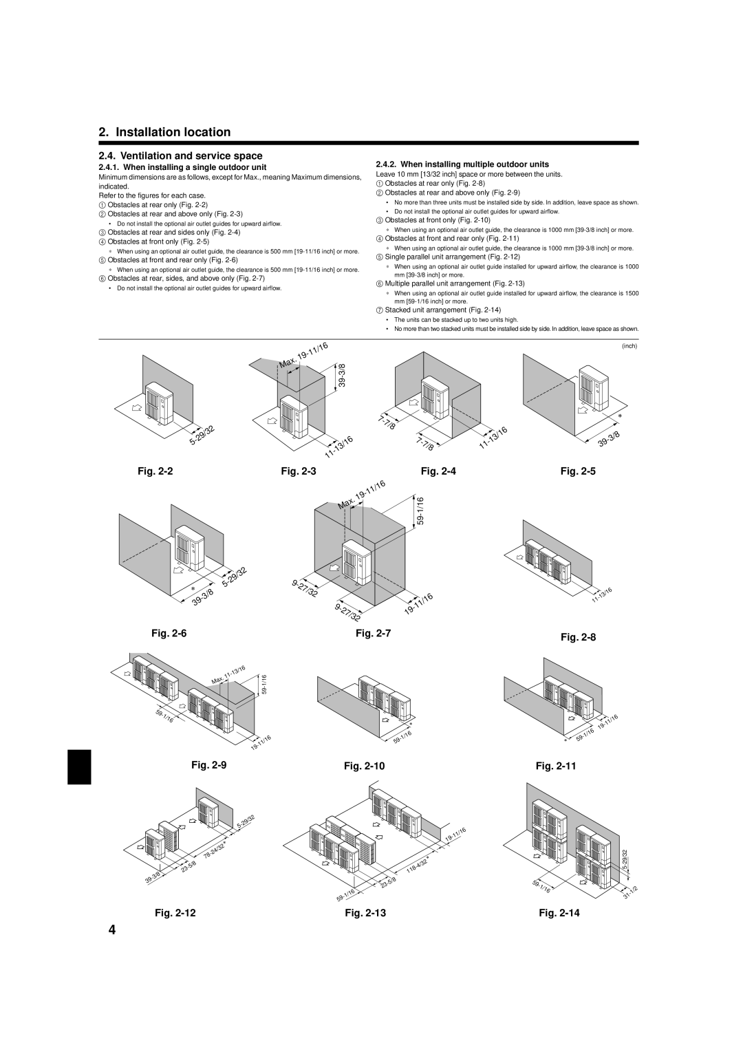
 -29/32