Standard Cabling Diagram
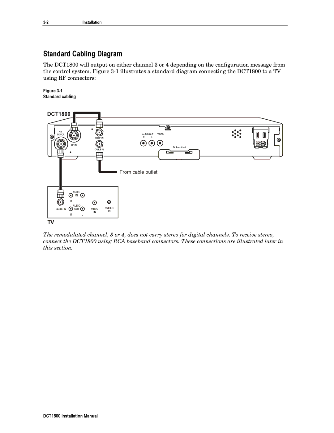
The DCT1800 will output on either channel 3 or 4 depending on the configuration message from the control system. Figure
Figure
Standard cabling
DCT1800 

TO |
| AUDIO OUT VIDEO | |
TV/VCR |
| ||
| TO RF IN | R | L |
RF IN
TV Pass Card
CABLE IN
![]() From cable outlet
From cable outlet
AUDIO
IN
| R | L |
|
| AUDIO | VIDEO | SVIDEO |
CABLE IN | OUT | ||
| R | IN | IN |
| L |
|
TV
The remodulated channel, 3 or 4, does not carry stereo for digital channels. To receive stereo, connect the DCT1800 using RCA baseband connectors. These connections are illustrated later in this section.
DCT1800 Installation Manual