Rear Panel
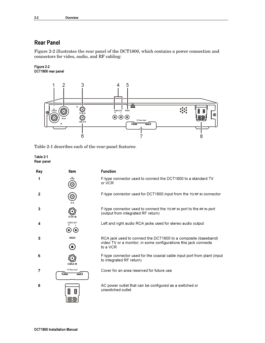
Figure 2-2 illustrates the rear panel of the DCT1800, which contains a power connection and connectors for video, audio, and RF cabling:
Figure
DCT1800 rear panel
1 | 2 | 3 | 4 | 5 |
TO |
| AUDIO OUT VIDEO | |
TV/VCR |
| ||
| TO RF IN | R | L |
RF IN
CABLE IN
TV Pass Card
|
|
|
|
| 8 |
|
|
|
|
| |
6 | 7 | ||||
Table
Table
Rear panel
KeyItem
1 |
| TO |
|
| TV/VCR |
2 |
|
|
|
| RF IN |
3 |
|
|
4 | TO RF IN | |
R | L | |
| AUDIO OUT | |
5 | VIDEO | |
| ||
6 |
| |
7 | CABLE IN | |
TV Pass Card | ||
|
8
Function
Left and right audio RCA jacks used for stereo audio output
RCA jack used to connect the DCT1800 to a composite (baseband) video TV or a monitor; in some configurations this jack connects to a VCR
Cover for an area reserved for future use
AC power outlet that can be configured as a switched or unswitched outlet
DCT1800 Installation Manual