(3) 440 MHz band
The signals from the limiter amplifier (RF unit; IC301) changes the reactance of a diode (VCO unit; D321) to mod- ulate the oscillated signal at the
(4) 1200 MHz band
The signals from the limiter amplifier (RF unit: IC301) changes the reactance of a diode (VCO unit; D352) to mod- ulate the oscillated signal at the
The amplified signal is passed through the antenna switch- ing circuit (D101 and D102),
(3) 440 MHz PA
The signal from the LO amplifiers (Q823) is passed through the Tx/Rx switch (D804 and D805), and is amplified at the buffer amplifier (Q135) and the YGR amplifier (Q136). The amplified signal is applied to the driver amplifier (Q921), and is then amplified at the power amplifier (Q922) to obtain 5.0 W of RF power.
The amplified signal is passed through the antenna switch- ing circuit (D402 and D403),
(4) 1200 MHz PA
The signal from the LO amplifiers (Q824) is passed through the Tx/Rx switch (D806 and D807), and is amplified at the
4-2-3 DRIVE/POWER AMPLIFIER CIRCUITS (RF UNIT)
The amplifier circuit amplifies the VCO oscillating signal to the output power level.
(1) 50 MHz PA
The signal from the LO amplifiers (Q821) is amplified at the
The amplified signal is passed through the antenna switch- ing circuit (D101 and D102) and
(2) 144 MHz PA
The signal from the LO amplifiers (Q822) is passed through the Tx/Rx switch (D802 and D803), and is amplified at the
The amplified signal is passed through the antenna switch- ing circuit (D51 and D52),
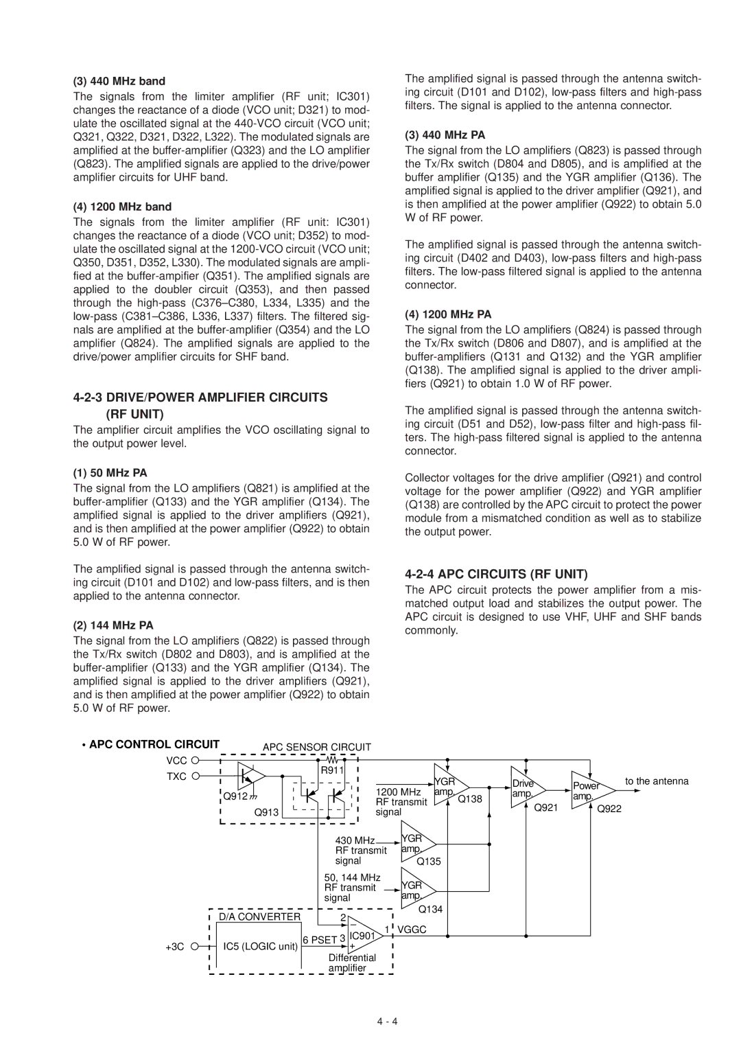
Collector voltages for the drive amplifier (Q921) and control voltage for the power amplifier (Q922) and YGR amplifier (Q138) are controlled by the APC circuit to protect the power module from a mismatched condition as well as to stabilize the output power.
4-2-4 APC CIRCUITS (RF UNIT)
The APC circuit protects the power amplifier from a mis- matched output load and stabilizes the output power. The APC circuit is designed to use VHF, UHF and SHF bands commonly.
• APC CONTROL CIRCUIT | APC SENSOR CIRCUIT |
VCC | R911 |
|
|
|
TXC |
|
| YGR | |
|
|
| ||
|
|
|
| |
| Q912 | 1200 MHz | amp. | |
| RF transmit | Q138 | ||
| Q913 | signal |
| |
| 430 MHz |
| YGR |
|
| RF transmit | amp. |
| |
| signal |
| Q135 | |
50, 144 MHz
RF transmit YGR
signalamp.
| D/A CONVERTER |
| 2 – |
| Q134 |
|
| 1 | VGGC | ||
+3C | IC5 (LOGIC unit) | 6 | PSET 3 IC901 | ||
| + |
|
| ||
|
|
| Differential |
|
|
|
|
| amplifier |
|
|
Drive | Power | to the antenna | |||||
amp. |
| amp. |
|
|
| ||
| Q921 |
| Q922 |
|
| ||
|
|
|
| ||||
|
|
|
|
|
|
|
|
4 - 4
