SECTION 4 CIRCUIT DESCRIPTION
4-1 RECEIVER CIRCUITS
4-1-1 DUPLEXER CIRCUIT (RF UNIT)
The transceiver has a duplexer
The RF signals below UHF pass through the duplexer circuit and are separated into VHF (50 MHz, 144 MHz and WFM band) and UHF (440 MHz band) signals. The
The VHF signals are applied to the another duplexer circuit for separation into 50 MHz and above WFM band signals. The
The separated signals are applied to each RF circuits.
4-1-2 ANTENNA SWITCHING CIRCUITS (RF UNIT)
The antenna switching circuit functions as a
Thus, transmit signals are blocked from entering the receiv- er circuits. The antenna switching circuit employs a 1/4λ type diode switching system. The passed signals are then applied to each RF amplifier circuit.
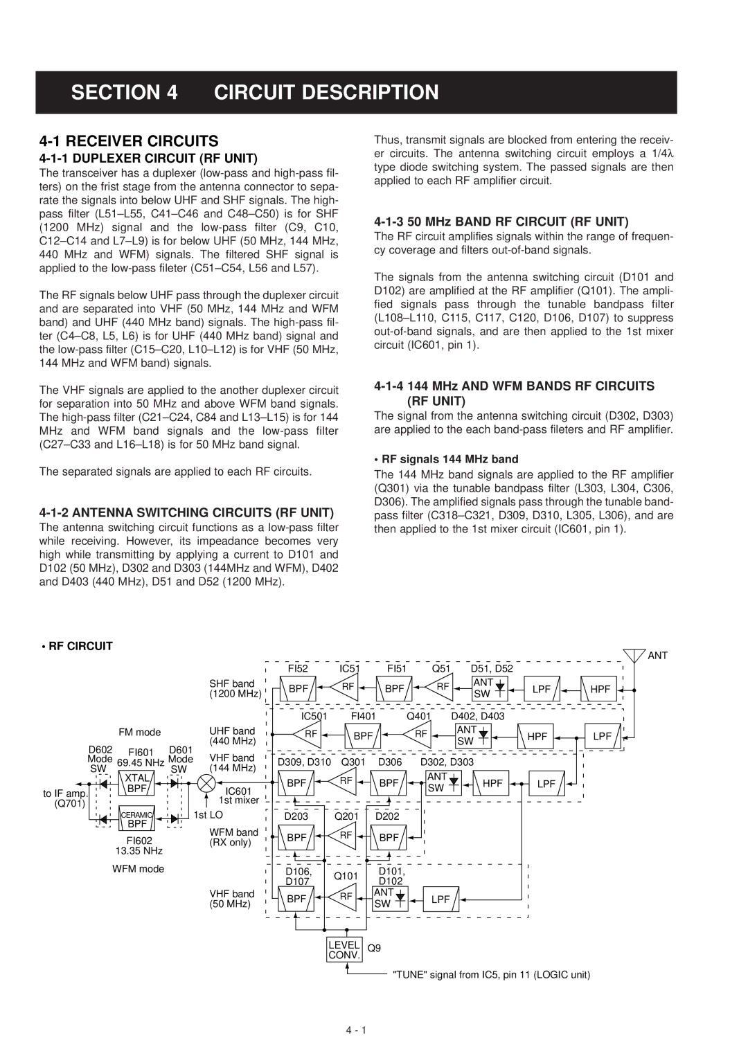
4-1-3 50 MHz BAND RF CIRCUIT (RF UNIT)
The RF circuit amplifies signals within the range of frequen- cy coverage and filters
The signals from the antenna switching circuit (D101 and D102) are amplified at the RF amplifier (Q101). The ampli- fied signals pass through the tunable bandpass filter
4-1-4 144 MHz AND WFM BANDS RF CIRCUITS (RF UNIT)
The signal from the antenna switching circuit (D302, D303) are applied to the each
• RF signals 144 MHz band
The 144 MHz band signals are applied to the RF amplifier (Q301) via the tunable bandpass filter (L303, L304, C306, D306). The amplified signals pass through the tunable band- pass filter
• RF CIRCUIT
SHF band (1200 MHz)
|
|
|
|
|
| ANT | |
FI52 | IC51 | FI51 | Q51 | D51, D52 |
|
| |
BPF | RF | BPF | RF | ANT | LPF | HPF | |
SW | |||||||
|
|
|
|
|
| ||
IC501 | FI401 | Q401 |
| D402, D403 |
|
|
| FM mode |
| UHF band | RF | BPF |
| RF | ANT | HPF | LPF | |
|
|
| (440 MHz) |
|
|
| SW | ||||
D602 | FI601 | D601 |
|
|
|
|
|
|
| ||
VHF band |
|
|
|
|
|
|
|
| |||
Mode | 69.45 NHz Mode | D309, D310 | Q301 |
| D306 | D302, D303 |
|
| |||
SW | XTAL | SW | (144 MHz) |
|
|
|
| ANT |
|
|
|
|
|
| BPF | RF |
| BPF | HPF | LPF |
| ||
to IF amp. | BPF |
| IC601 |
| SW |
| |||||
|
|
|
|
|
|
|
| ||||
|
|
|
|
|
|
|
|
|
| ||
(Q701) |
|
| 1st mixer |
|
|
|
|
|
|
|
|
|
| 1st LO |
|
|
|
|
|
|
|
| |
| CERAMIC |
| D203 | Q201 |
| D202 |
|
|
|
| |
| BPF |
| WFM band |
|
|
|
|
|
|
|
|
| FI602 |
| BPF | RF |
| BPF |
|
|
|
| |
|
| (RX only) |
|
|
|
|
| ||||
|
|
|
|
|
|
|
|
|
| ||
| 13.35 NHz |
|
|
|
|
|
|
|
|
|
|
WFM mode |
|
| D106, | Q101 |
| D101, |
|
|
|
| |
|
|
|
| D107 |
| D102 |
|
|
|
| |
|
|
|
|
|
|
|
|
|
| ||
|
|
| VHF band | BPF | RF |
| ANT | LPF |
|
|
|
|
|
| (50 MHz) |
| SW |
|
|
| |||
|
|
|
|
|
|
|
|
|
| ||
|
|
|
| LEVEL | Q9 |
|
|
|
| ||
|
|
|
| CONV. |
|
|
|
|
|
| |
|
|
|
|
|
|
| "TUNE" signal from IC5, pin 11 (LOGIC unit) |
| |||
4 - 1