Electrical Connections Class 1 wiring methods must be used for field wiring connections to terminals of a class 2 circuit. It is the responsibility of the owner/operator to arrange for these procedures to be performed by a licensed electrical contractor and ensure conformance to all applicable codes including local codes peculiar to your municipality/city/county and state. Wire size and insulation type should be as required by NEC (National Electrical Code) and local codes.
Warning: Never connect this generator to the electrical system of any building unless a licensed electrician has installed an approved transfer switch. The national electrical code (NEC) requires that connection of a generator to any electrical circuit normally powered by means of an electric utility must be connected by means of approved transfer switch equipment to isolate the electrical circuit from the utility distribution system when the generator is operating. Failure to isolate the electrical circuits by such means may result in injury or death to utility power workers due to backfeed of electrical energy onto the utility lines.
Warning: Incorrect installation of this generator set could result in property damage, injury or death. Connection of the generator to its fuel source must be done by a qualified professional technician or contractor.
WARNING: Be sure the system is properly grounded before applying power. Do not apply AC power before you ensure that grounds are connected. Electrical shock can cause serious or fatal injury. NEC requires that the frame and exposed conductive surfaces (metal parts) be connected to an approved earth ground. Local codes may also require proper grounding of generator systems.
Intended Use The intended purpose of this generator set is to provide emergency power when the main utility power supply is interrupted. Therefore, it is important that all the wiring that connects the generator set with your house, transfer switch, distribution box, battery charger, etc. be properly installed.
Circuit Protection Circuit protection is not provided within the generator. Circuit Breaker protection is an option. If purchased with your generator, the breaker box is mounted to the generator prior to shipment. If the optional circuit breaker protection was not ordered, see “GLC Circuit Breaker & Wire Size Data” in Appendix A for recommendations.
Wire Size Proper lead wire from the circuit breaker to the automatic transfer switch (or load switching device) is mandatory. See transfer switch information for connection information. When connecting the generator output to an electrical load, a UL listed circuit breaker with the appropriate ratings must be provided within 25 feet of the generator set. Use only copper wires.
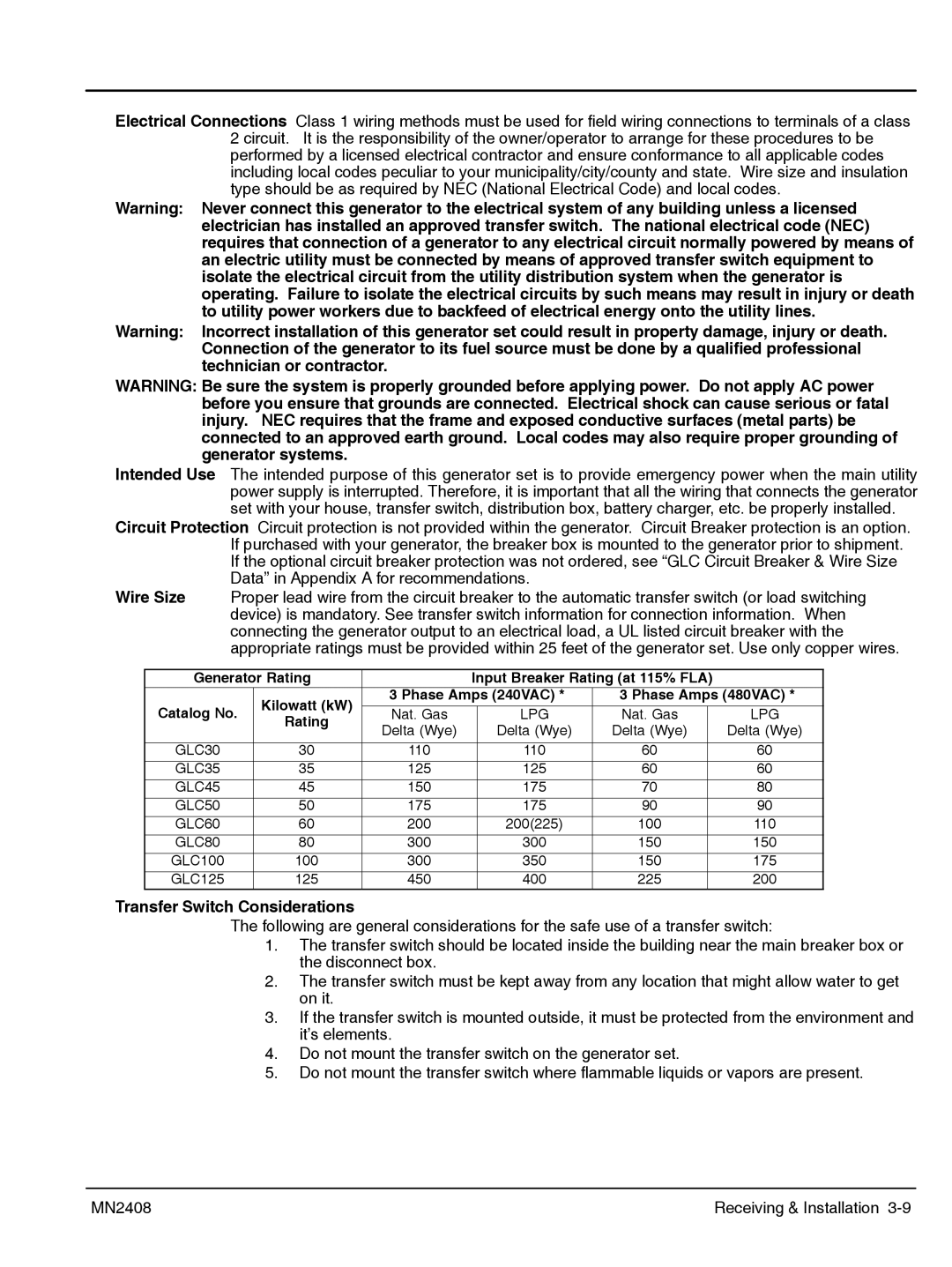
Generator Rating |
| Input Breaker Rating (at 115% FLA) |
| ||||
| Kilowatt (kW) | 3 Phase Amps (240VAC) * | 3 Phase Amps (480VAC) * | ||||
Catalog No. |
|
|
|
|
|
| |
Nat. Gas |
| LPG | Nat. Gas |
| LPG | ||
Rating |
|
| |||||
| Delta (Wye) |
| Delta (Wye) | Delta (Wye) |
| Delta (Wye) | |
|
|
|
| ||||
|
|
|
|
|
|
|
|
GLC30 | 30 | 110 |
| 110 | 60 |
| 60 |
GLC35 | 35 | 125 |
| 125 | 60 |
| 60 |
GLC45 | 45 | 150 |
| 175 | 70 |
| 80 |
GLC50 | 50 | 175 |
| 175 | 90 |
| 90 |
GLC60 | 60 | 200 |
| 200(225) | 100 |
| 110 |
GLC80 | 80 | 300 |
| 300 | 150 |
| 150 |
GLC100 | 100 | 300 |
| 350 | 150 |
| 175 |
GLC125 | 125 | 450 |
| 400 | 225 |
| 200 |
Transfer Switch Considerations
The following are general considerations for the safe use of a transfer switch:
1.The transfer switch should be located inside the building near the main breaker box or the disconnect box.
2.The transfer switch must be kept away from any location that might allow water to get on it.
3.If the transfer switch is mounted outside, it must be protected from the environment and it’s elements.
4.Do not mount the transfer switch on the generator set.
5.Do not mount the transfer switch where flammable liquids or vapors are present.
MN2408 | Receiving & Installation |