Manual Start/Stop
To manually Start the
1.When the “Manual Run”
2.When the engine start delay time expires, an engine RUN and CRANK output signal will be initiated. (The RUN output may be programmed to only energize when a start signal is initiated and an engine speed signal is detected.)
3.When the engine starts and begins to accelerate to nominal speed, the controllers speed sensor will terminate the CRANK output when engine speed reaches approximately 20% speed (i.e. CRANK DISCONNECT speed setpoint).
To manually Stop the
Automatic Start/Stop
To setup the generator for automatic operation, set the Master Control switch to the “Auto Start” position. The following happens:
1.The engine will automatically start upon activation of the remote start contact input. The remote device initiates a start sequence upon contact closure.
2.When the remote start signal is activated, the engine will start as per the sequence of operation described for the manual start sequence.
3.The automatic stop sequence will be initiated by removal of the remote start signal.
4.When the start signal is removed, a cool down delay function will be initiated.
5.When the cool down time delay period expires (typically 5 minutes), the controllers RUN output will be immediately terminated which will initiate the engine to stop.
Automatic Fault Shutdown
When a fault circuit is programmed as a SHUTDOWN, the engine will immediately stop when the fault is activated. A specific shutdown fault can be programmed with a definite time transient delay period that must expire before the shutdown is activated. The stop sequence will cause the controllers RUN output to be immediately terminated which will cause the engine to stop.
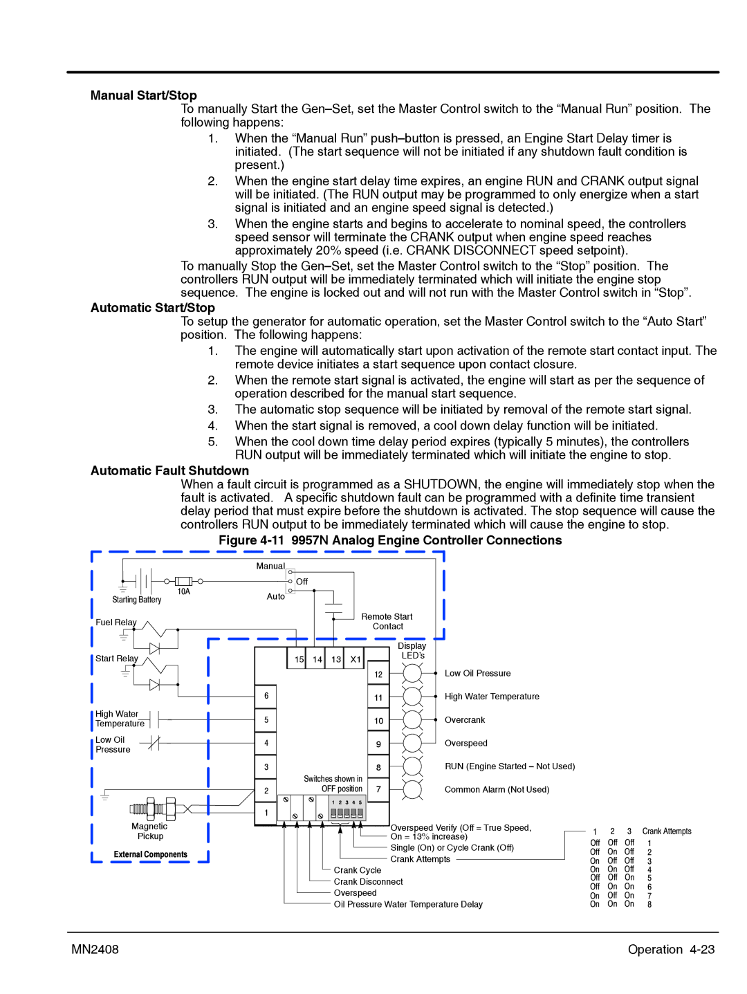
Figure 4-11 9957N Analog Engine Controller Connections
Starting Battery
Fuel Relay
Start Relay
High Water
Temperature
Low Oil
Pressure
10A
Manual |
|
|
|
|
|
Off |
|
|
|
|
|
Auto |
|
|
|
|
|
|
|
|
| Remote Start |
|
|
|
|
| Contact |
|
|
|
|
| Display |
|
15 | 14 | 13 | X1 | LED’s |
|
|
| ||||
|
|
|
| 12 | Low Oil Pressure |
6 |
|
|
| 11 | High Water Temperature |
5 |
|
|
| 10 | Overcrank |
4 |
|
|
| 9 | Overspeed |
3 |
|
|
| 8 | RUN (Engine Started – Not Used) |
Switches shown in |
| ||||
2 | OFF position 7 | Common Alarm (Not Used) | |||
1 |
|
|
|
|
|
Magnetic
Pickup
External Components
Overspeed Verify (Off = True Speed, |
On = 13% increase) |
Single (On) or Cycle Crank (Off) |
Crank Attempts |
Crank Cycle |
Crank Disconnect |
Overspeed |
Oil Pressure Water Temperature Delay |
1 | 2 | 3 Crank Attempts |
Off Off Off 1
Off On Off 2
On Off Off 3
On On Off 4
Off Off On 5
Off On On 6
On Off On 7
On On On 8
MN2408 | Operation |