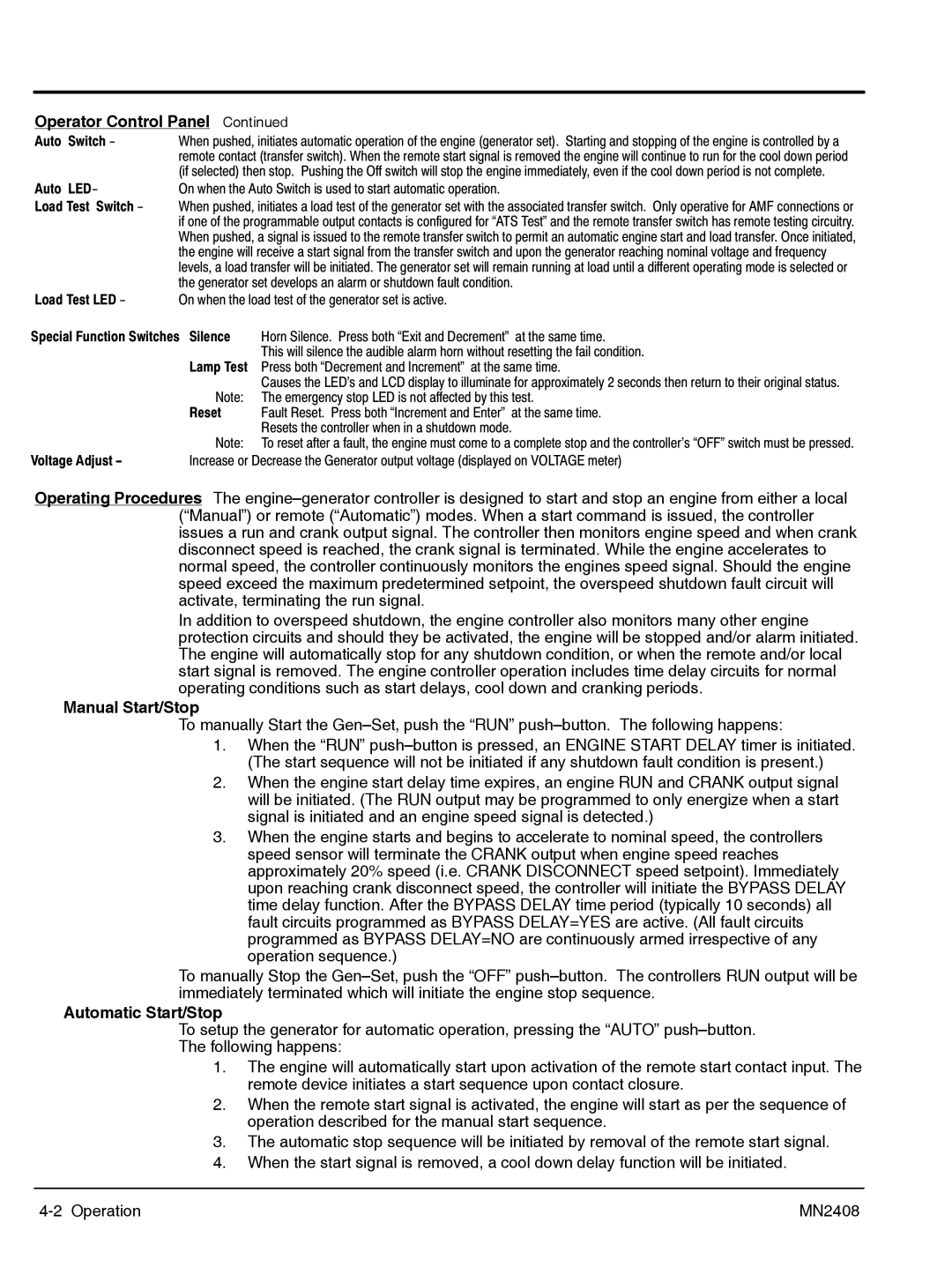
Operator Control Panel Continued
Auto Switch - | When pushed, initiates automatic operation of the engine (generator set). Starting and stopping of the engine is controlled by a | |
| remote contact (transfer switch). When the remote start signal is removed the engine will continue to run for the cool down period | |
| (if selected) then stop. Pushing the Off switch will stop the engine immediately, even if the cool down period is not complete. | |
Auto LED- | On when the Auto Switch is used to start automatic operation. | |
Load Test Switch - | When pushed, initiates a load test of the generator set with the associated transfer switch. Only operative for AMF connections or | |
| if one of the programmable output contacts is configured for •ATS Test" and the remote transfer switch has remote testing circuitry. | |
| When pushed, a signal is issued to the remote transfer switch to permit an automatic engine start and load transfer. Once initiated, | |
| the engine will receive a start signal from the transfer switch and upon the generator reaching nominal voltage and frequency | |
| levels, a load transfer will be initiated. The generator set will remain running at load until a different operating mode is selected or | |
| the generator set develops an alarm or shutdown fault condition. | |
Load Test LED - | On when the load test of the generator set is active. | |
Special Function Switches Silence | Horn Silence. Press both •Exit and Decrement" at the same time. | |
|
| This will silence the audible alarm horn without resetting the fail condition. |
| Lamp Test Press both •Decrement and Increment" at the same time. | |
|
| Causes the LED's and LCD display to illuminate for approximately 2 seconds then return to their original status. |
| Note: | The emergency stop LED is not affected by this test. |
| Reset | Fault Reset. Press both •Increment and Enter" at the same time. |
|
| Resets the controller when in a shutdown mode. |
| Note: | To reset after a fault, the engine must come to a complete stop and the controller's •OFF" switch must be pressed. |
Voltage Adjust - | Increase or Decrease the Generator output voltage (displayed on VOLTAGE meter) | |
Operating Procedures The
In addition to overspeed shutdown, the engine controller also monitors many other engine protection circuits and should they be activated, the engine will be stopped and/or alarm initiated. The engine will automatically stop for any shutdown condition, or when the remote and/or local start signal is removed. The engine controller operation includes time delay circuits for normal operating conditions such as start delays, cool down and cranking periods.
Manual Start/Stop
To manually Start the
1.When the “RUN”
2.When the engine start delay time expires, an engine RUN and CRANK output signal will be initiated. (The RUN output may be programmed to only energize when a start signal is initiated and an engine speed signal is detected.)
3.When the engine starts and begins to accelerate to nominal speed, the controllers speed sensor will terminate the CRANK output when engine speed reaches approximately 20% speed (i.e. CRANK DISCONNECT speed setpoint). Immediately upon reaching crank disconnect speed, the controller will initiate the BYPASS DELAY time delay function. After the BYPASS DELAY time period (typically 10 seconds) all fault circuits programmed as BYPASS DELAY=YES are active. (All fault circuits programmed as BYPASS DELAY=NO are continuously armed irrespective of any operation sequence.)
To manually Stop the
Automatic Start/Stop
To setup the generator for automatic operation, pressing the “AUTO”
The following happens:
1.The engine will automatically start upon activation of the remote start contact input. The remote device initiates a start sequence upon contact closure.
2.When the remote start signal is activated, the engine will start as per the sequence of operation described for the manual start sequence.
3.The automatic stop sequence will be initiated by removal of the remote start signal.
4.When the start signal is removed, a cool down delay function will be initiated.
MN2408 |
