|
|
| Pre |
|
|
| |
| n |
|
| n |
| ||
|
|
|
|
|
|
|
|
|
|
|
|
|
|
|
|
|
|
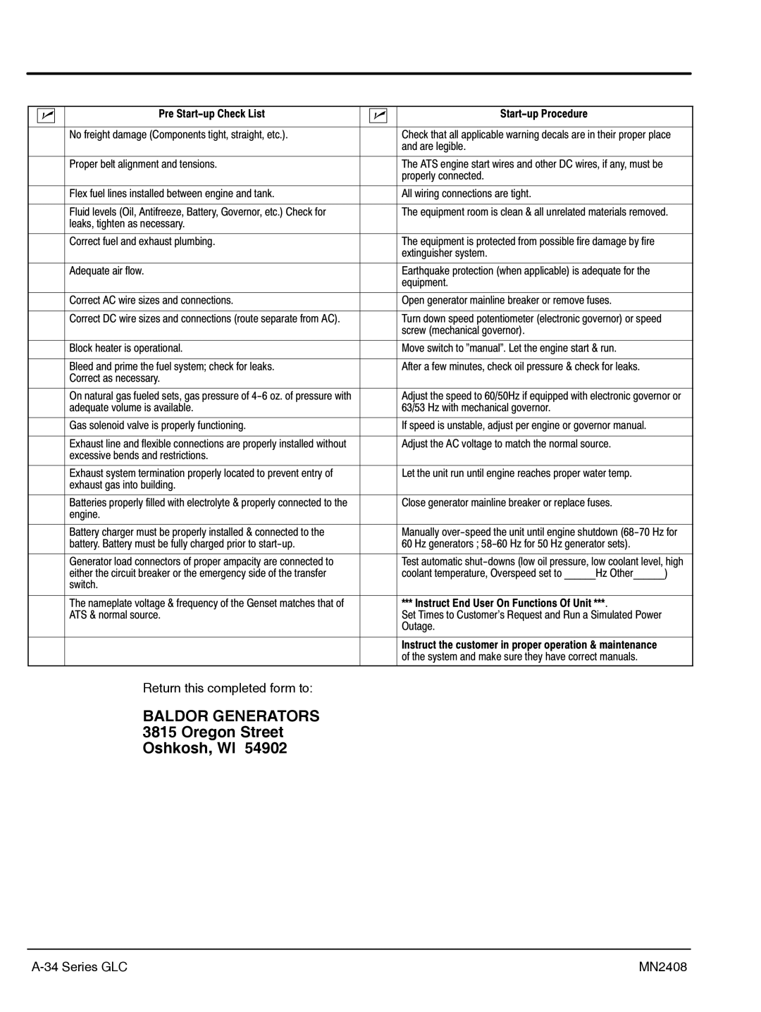
| No freight damage (Components tight, straight, etc.). |
|
|
| Check that all applicable warning decals are in their proper place |
|
|
|
|
|
|
| and are legible. |
|
|
|
|
|
|
|
|
|
|
| Proper belt alignment and tensions. |
|
|
| The ATS engine start wires and other DC wires, if any, must be |
|
|
|
|
|
|
| properly connected. |
|
|
|
|
|
|
|
|
|
|
| Flex fuel lines installed between engine and tank. |
|
|
| All wiring connections are tight. |
|
|
|
|
|
|
|
|
|
|
| Fluid levels (Oil, Antifreeze, Battery, Governor, etc.) Check for |
|
|
| The equipment room is clean & all unrelated materials removed. |
|
|
| leaks, tighten as necessary. |
|
|
|
|
|
|
|
|
|
|
|
|
|
|
| Correct fuel and exhaust plumbing. |
|
|
| The equipment is protected from possible fire damage by fire |
|
|
|
|
|
|
| extinguisher system. |
|
|
|
|
|
|
|
|
|
|
| Adequate air flow. |
|
|
| Earthquake protection (when applicable) is adequate for the |
|
|
|
|
|
|
| equipment. |
|
|
|
|
|
|
|
|
|
|
| Correct AC wire sizes and connections. |
|
|
| Open generator mainline breaker or remove fuses. |
|
|
|
|
|
|
|
|
|
|
| Correct DC wire sizes and connections (route separate from AC). |
|
|
| Turn down speed potentiometer (electronic governor) or speed |
|
|
|
|
|
|
| screw (mechanical governor). |
|
|
|
|
|
|
|
|
|
|
| Block heater is operational. |
|
|
| Move switch to "manual". Let the engine start & run. |
|
|
|
|
|
|
|
|
|
|
| Bleed and prime the fuel system; check for leaks. |
|
|
| After a few minutes, check oil pressure & check for leaks. |
|
|
| Correct as necessary. |
|
|
|
|
|
|
|
|
|
|
|
|
|
|
| On natural gas fueled sets, gas pressure of |
|
|
| Adjust the speed to 60/50Hz if equipped with electronic governor or |
|
|
| adequate volume is available. |
|
|
| 63/53 Hz with mechanical governor. |
|
|
|
|
|
|
|
|
|
|
| Gas solenoid valve is properly functioning. |
|
|
| If speed is unstable, adjust per engine or governor manual. |
|
|
|
|
|
|
|
|
|
|
| Exhaust line and flexible connections are properly installed without |
|
|
| Adjust the AC voltage to match the normal source. |
|
|
| excessive bends and restrictions. |
|
|
|
|
|
|
|
|
|
|
|
|
|
|
| Exhaust system termination properly located to prevent entry of |
|
|
| Let the unit run until engine reaches proper water temp. |
|
|
| exhaust gas into building. |
|
|
|
|
|
|
|
|
|
|
|
|
|
|
| Batteries properly filled with electrolyte & properly connected to the |
|
|
| Close generator mainline breaker or replace fuses. |
|
|
| engine. |
|
|
|
|
|
|
|
|
|
|
|
|
|
|
| Battery charger must be properly installed & connected to the |
|
|
| Manually |
|
|
| battery. Battery must be fully charged prior to |
|
|
| 60 Hz generators ; |
|
|
|
|
|
|
|
|
|
|
| Generator load connectors of proper ampacity are connected to |
|
|
| Test automatic |
|
|
| either the circuit breaker or the emergency side of the transfer |
|
|
| coolant temperature, Overspeed set to ______Hz Other______) |
|
|
| switch. |
|
|
|
|
|
|
|
|
|
|
|
|
|
|
| The nameplate voltage & frequency of the Genset matches that of |
|
|
| *** Instruct End User On Functions Of Unit ***. |
|
|
| ATS & normal source. |
|
|
| Set Times to Customer's Request and Run a Simulated Power |
|
|
|
|
|
|
| Outage. |
|
|
|
|
|
|
|
|
|
|
|
|
|
|
| Instruct the customer in proper operation & maintenance |
|
|
|
|
|
|
| of the system and make sure they have correct manuals. |
Return this completed form to:
BALDOR GENERATORS
3815 Oregon Street
Oshkosh, WI 54902
| MN2408 |
