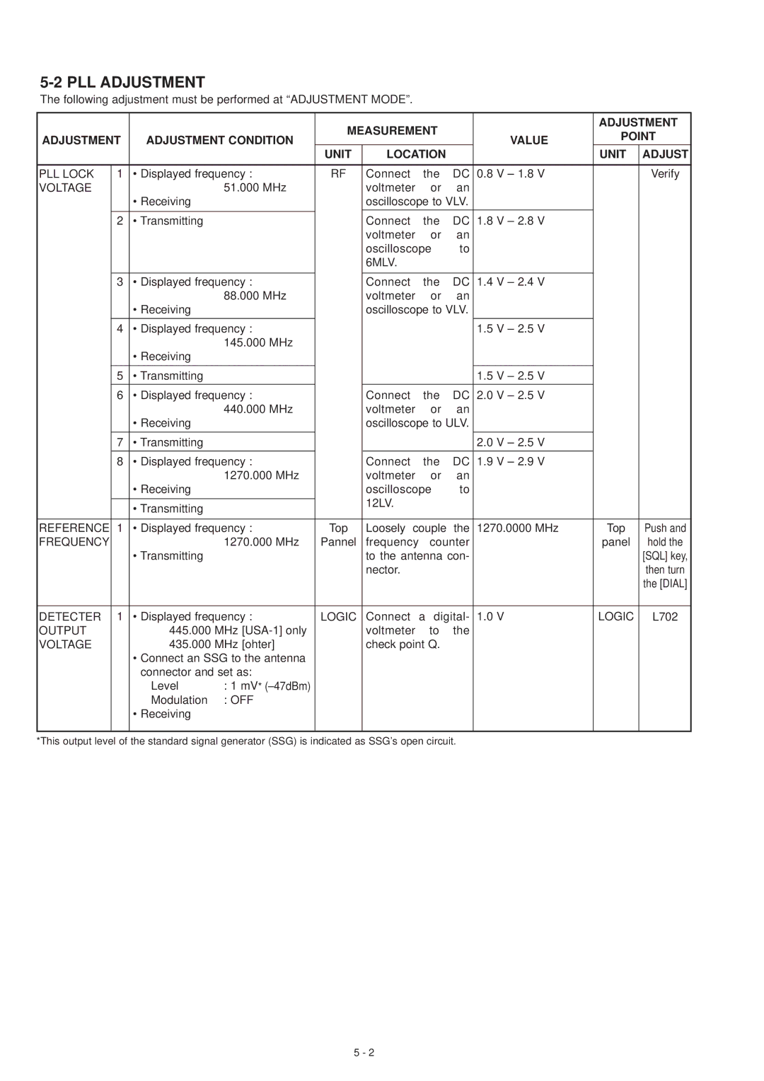
5-2 PLL ADJUSTMENT
The following adjustment must be performed at “ADJUSTMENT MODE”.
|
|
|
| MEASUREMENT |
|
|
| ADJUSTMENT | |||
ADJUSTMENT | ADJUSTMENT CONDITION |
|
| VALUE | POINT | ||||||
|
|
|
|
| |||||||
|
|
|
| UNIT | LOCATION |
|
|
| UNIT | ADJUST | |
|
|
|
|
|
|
|
|
|
|
| |
PLL LOCK | 1 | • Displayed frequency : | RF | Connect | the | DC | 0.8 | V – 1.8 V |
| Verify | |
VOLTAGE |
|
| 51.000 MHz |
| voltmeter | or | an |
|
|
|
|
|
| • Receiving |
|
| oscilloscope to VLV. |
|
|
|
| ||
|
|
|
|
|
|
|
|
|
|
|
|
|
|
|
|
|
|
|
|
|
|
|
|
| 2 | • Transmitting |
|
| Connect | the | DC | 1.8 | V – 2.8 V |
|
|
|
|
|
|
| voltmeter | or | an |
|
|
|
|
|
|
|
|
| oscilloscope | to |
|
|
|
| |
|
|
|
|
| 6MLV. |
|
|
|
|
|
|
|
|
|
|
|
|
|
|
|
|
| |
| 3 | • Displayed frequency : |
| Connect | the | DC | 1.4 | V – 2.4 V |
|
| |
|
|
| 88.000 MHz |
| voltmeter | or | an |
|
|
|
|
|
| • Receiving |
|
| oscilloscope to VLV. |
|
|
|
| ||
|
|
|
|
|
|
|
|
|
|
| |
| 4 | • Displayed frequency : |
|
|
|
| 1.5 | V – 2.5 V |
|
| |
|
|
| 145.000 MHz |
|
|
|
|
|
|
|
|
|
| • Receiving |
|
|
|
|
|
|
|
|
|
|
|
|
|
|
|
|
|
|
|
|
|
| 5 | • Transmitting |
|
|
|
|
| 1.5 | V – 2.5 V |
|
|
|
|
|
|
|
|
|
|
|
|
| |
| 6 | • Displayed frequency : |
| Connect | the | DC | 2.0 | V – 2.5 V |
|
| |
|
|
| 440.000 MHz |
| voltmeter | or | an |
|
|
|
|
|
| • Receiving |
|
| oscilloscope to ULV. |
|
|
|
| ||
|
|
|
|
|
|
|
|
|
|
|
|
| 7 | • Transmitting |
|
|
|
|
| 2.0 | V – 2.5 V |
|
|
|
|
|
|
|
|
|
|
|
|
| |
| 8 | • Displayed frequency : |
| Connect | the | DC | 1.9 | V – 2.9 V |
|
| |
|
|
| 1270.000 MHz |
| voltmeter | or | an |
|
|
|
|
|
| • Receiving |
|
| oscilloscope | to |
|
|
|
| |
|
|
|
|
| 12LV. |
|
|
|
|
|
|
|
| • Transmitting |
|
|
|
|
|
|
|
| |
|
|
|
|
|
|
|
|
|
|
| |
|
|
|
|
|
|
|
|
| |||
REFERENCE | 1 | • Displayed frequency : | Top | Loosely couple | the | 1270.0000 MHz | Top | Push and | |||
FREQUENCY |
|
| 1270.000 MHz | Pannel | frequency | counter |
|
| panel | hold the | |
|
| • Transmitting |
|
| to the antenna con- |
|
|
| [SQL] key, | ||
|
|
|
|
| nector. |
|
|
|
|
| then turn |
|
|
|
|
|
|
|
|
|
|
| the [DIAL] |
|
|
|
|
|
|
|
|
|
| ||
DETECTER | 1 | • Displayed frequency : | LOGIC | Connect | a digital- | 1.0 | V | LOGIC | L702 | ||
OUTPUT |
| 445.000 MHz |
| voltmeter | to | the |
|
|
|
| |
VOLTAGE |
| 435.000 MHz [ohter] |
| check point Q. |
|
|
|
|
| ||
|
| • Connect an SSG to the antenna |
|
|
|
|
|
|
|
| |
|
| connector and set as: |
|
|
|
|
|
|
|
| |
|
| Level | : 1 mV* |
|
|
|
|
|
|
|
|
|
| Modulation | : OFF |
|
|
|
|
|
|
|
|
|
| • Receiving |
|
|
|
|
|
|
|
|
|
|
|
|
|
|
|
|
|
|
|
|
|
*This output level of the standard signal generator (SSG) is indicated as SSG’s open circuit.
5 - 2
