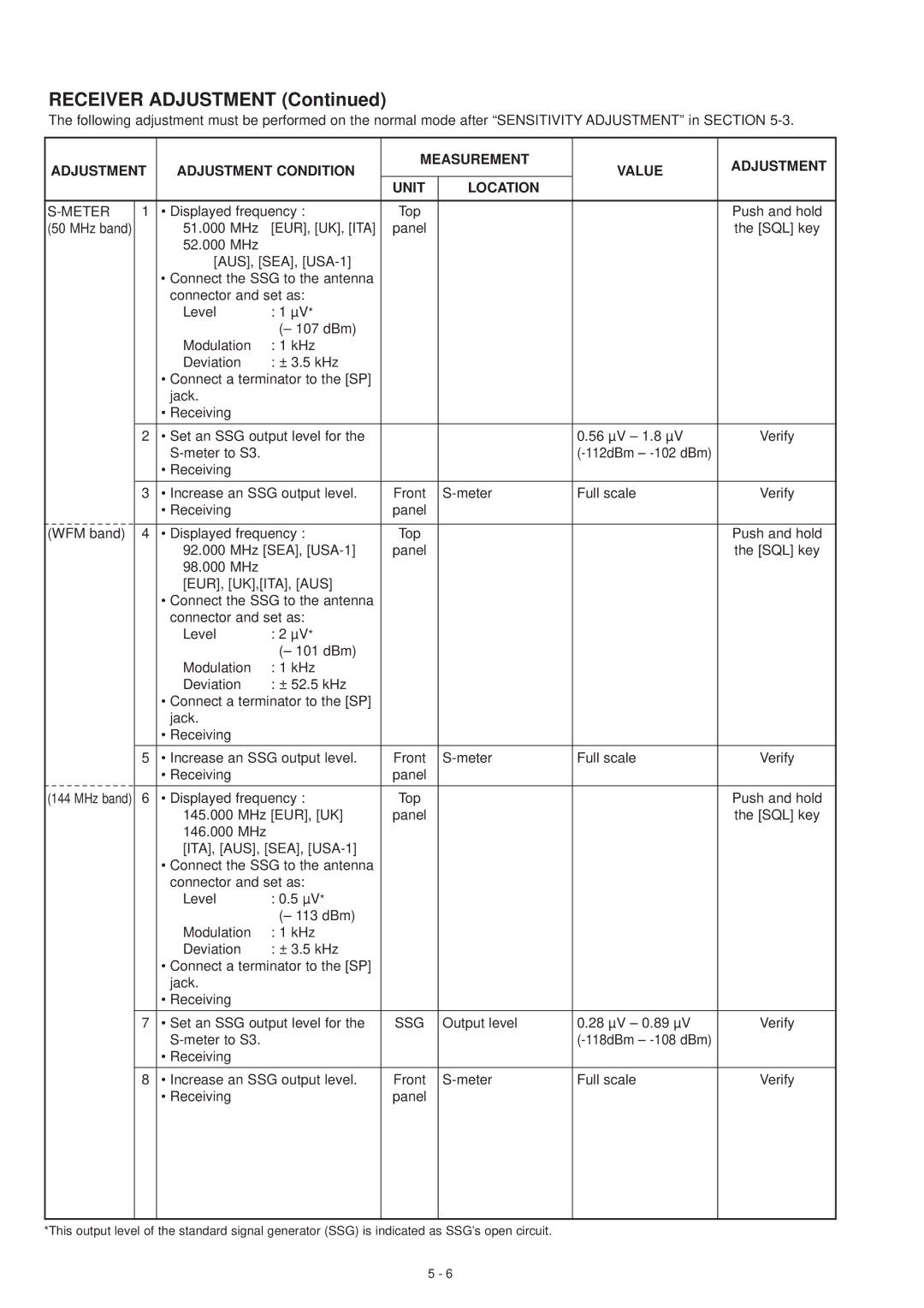
RECEIVER ADJUSTMENT (Continued)
The following adjustment must be performed on the normal mode after “SENSITIVITY ADJUSTMENT” in SECTION
ADJUSTMENT | ADJUSTMENT CONDITION | MEASUREMENT | VALUE | ADJUSTMENT | |||
|
| ||||||
|
|
|
| UNIT | LOCATION |
|
|
|
|
|
|
|
|
| |
| 1 | • Displayed frequency : | Top |
|
| Push and hold | |
(50 MHz band) |
| 51.000 MHz | [EUR], [UK], [ITA] | panel |
|
| the [SQL] key |
|
| 52.000 MHz |
|
|
|
|
|
|
| [AUS], [SEA], |
|
|
|
| |
|
| • Connect the SSG to the antenna |
|
|
|
| |
|
| connector and set as: |
|
|
|
| |
|
| Level | : 1 µV* |
|
|
|
|
|
|
| (– 107 dBm) |
|
|
|
|
|
| Modulation | : 1 kHz |
|
|
|
|
|
| Deviation | : ± 3.5 kHz |
|
|
|
|
•Connect a terminator to the [SP] jack.
•Receiving
2 | • Set an SSG output level for the |
| 0.56 µV – 1.8 µV | Verify | ||
|
|
|
| |||
|
| • Receiving |
|
|
| |
|
|
|
|
|
| |
3 | • Increase an SSG output level. | Front | Full scale | Verify | ||
|
| • Receiving | panel |
|
| |
|
|
|
|
|
| |
(WFM band) 4 | • Displayed frequency : | Top |
| Push and hold | ||
|
| 92.000 | MHz [SEA], | panel |
| the [SQL] key |
|
| 98.000 | MHz |
|
|
|
|
| [EUR], [UK],[ITA], [AUS] |
|
|
| |
•Connect the SSG to the antenna connector and set as:
Level | : 2 µV* |
| (– 101 dBm) |
Modulation | : 1 kHz |
Deviation | : ± 52.5 kHz |
•Connect a terminator to the [SP] jack.
•Receiving
5 | • Increase an SSG output level. | Front | Full scale | Verify | ||
|
| • Receiving |
| panel |
|
|
|
|
|
|
|
| |
(144 MHz band) 6 | • Displayed frequency : | Top |
| Push and hold | ||
|
| 145.000 | MHz [EUR], [UK] | panel |
| the [SQL] key |
|
| 146.000 | MHz |
|
|
|
|
| [ITA], [AUS], [SEA], |
|
|
| |
•Connect the SSG to the antenna connector and set as:
Level | : 0.5 µV* |
| (– 113 dBm) |
Modulation | : 1 kHz |
Deviation | : ± 3.5 kHz |
•Connect a terminator to the [SP] jack.
•Receiving
7 | • Set an SSG output level for the | SSG | Output level | 0.28 µV – 0.89 µV | Verify |
|
|
|
| ||
| • Receiving |
|
|
|
|
|
|
|
|
|
|
8 | • Increase an SSG output level. | Front | Full scale | Verify | |
| • Receiving | panel |
|
|
|
*This output level of the standard signal generator (SSG) is indicated as SSG’s open circuit.
5 - 6
