Manuals
/
MRV Communications
/
Home Audio
/
Stereo Amplifier
MRV Communications
EM316EDFA-BR
manual
Module Installation, Fiber Driver EM316EDFA User Guide
Models:
EM316EDFA-LPR
EM316EDFA-BR
1
14
44
44
Download
44 pages
43.38 Kb
11
12
13
14
15
16
17
18
Troubleshooting
Install
2.1.3EDFA Alarm Outputs
5.2.3.3“show running-config”
Other Commands
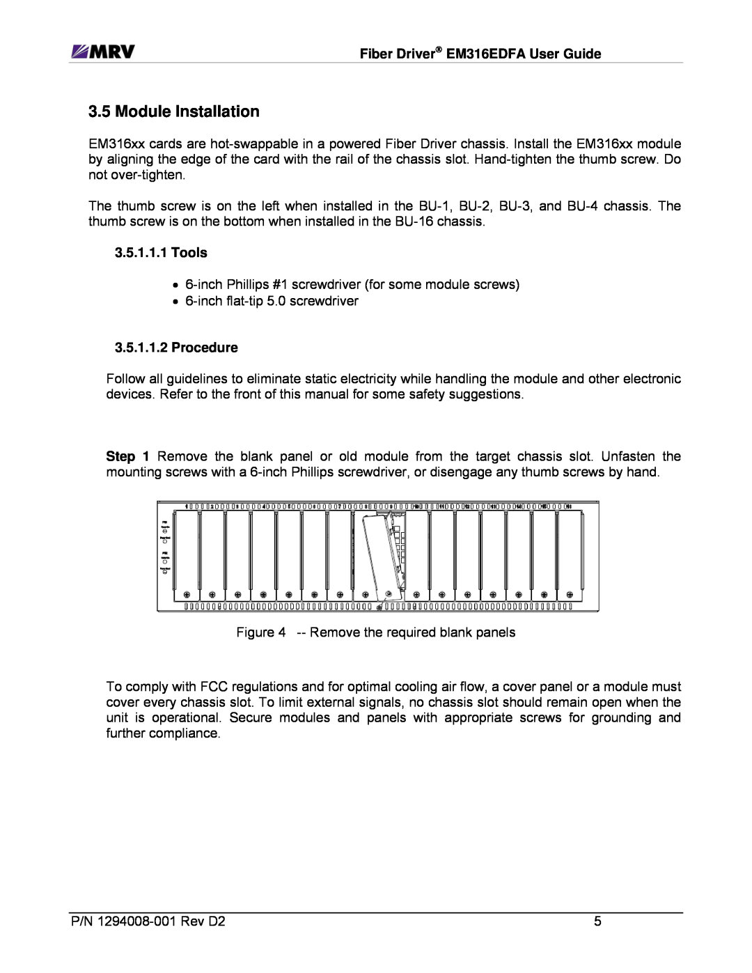
3.5.1.1.2Procedure
Safety
EDFA Features
DIP Switches
Page 14
Image 14
Page 13
Page 15
Page 14
Image 14
Page 13
Page 15
Contents
Erbium Doped Fiber Amplifier Booster
EM316EDFA-BR
EM316EDFA-LPR
Erbium Doped Fiber Inline Pre-Amplifier
2 Introduction to EM316EDFA Optical Amplifiers
3 Preparation and Installation
Table of Contents
5 Module Management
6 Appendix
Table of Figures
1.2 Copyright
1 Preliminary Considerations
1.1 Trademarks
1.3 Customer Support
Fiber Driver Chassis
1.4 Compliance
Fiber Driver EM316EDFA User Guide
Fiber Driver Modules
1.5.1Cautions and Warnings
1.5General Safety
1.5.2 Laser Safety
1.5.3 Laser Device Classifications
Fiber Driver EM316EDFA User Guide
1.5.4 Static Electricity
1.5.5 Workplace Preparation
Fiber Driver EM316EDFA User Guide
1.6 About This Manual
1.7 Latest Revision and Related Documents
Document Number
C-band pre-amplifier
2 Introduction to EM316EDFA Optical Amplifiers
Fiber Driver EM316EDFA User Guide
2.1.2EDFA Control Inputs
2.1 Features
2.1.3EDFA Alarm Outputs
3 Preparation and Installation
3.1 Unpacking the Fiber Driver Module
3.3 LEDs
3.4 DIP Switches
3.2 Front Panel
Fiber Driver EM316EDFA User Guide
3.5 Module Installation
3.5.1.1.2Procedure
3.5.1.1.1Tools
P/N 1294008-001Rev D2
4 EDFA Features
4.1 Network Management Control and Monitoring
4.1.3 Operating Parameters
4.1.2 EM316EDFA Alarm Output Pins
4.1.1 Management Control from the Network
5 Module Management
RS-232
5.1 Serial Console Interface
Fiber Driver EM316EDFA User Guide
Serial Port
5.2 EM316LNXNM-OTCommand Line Interface CLI
5.2.1 EM316LNXNM-OTBoot and CLI Login
P/N 1294008-001Rev D2
5.2.2 CLI Navigation
5.2.3.2“show log”
5.2.3 Login Context Commands and Examples
5.2.3.1“show version”
P/N 1294008-001Rev D2
5.2.3.3“show running-config”
fiberdriver# show running-config
P/N 1294008-001Rev D2
5.2.3.4“show startup-config”
fiberdriver# show startup-config
5.2.3.5 Configuring System Parameters
Fiber Driver EM316EDFA User Guide
5.2.4 Chassis Context
5.2.4.1“show”
P/N 1294008-001Rev D2
5.2.4.2 Other Commands
Fiber Driver EM316EDFA User Guide
Fiber Driver EM316EDFA User Guide
5.2.5 Slot Context Commands and Examples
Command
Description
Fiber Driver EM316EDFA User Guide 5.2.5.1 “?”
5.2.5.2“list”
Fiber Driver EM316EDFA User Guide 5.2.5.3 “show”
P/N 1294008-001Rev D2
EDFA-1
P/N 1294008-001Rev D2
EM316EDFAv
EM316EDFA
5.2.6 Port Context Commands and Examples
Fiber Driver EM316EDFA User Guide
5.2.6.1 “?”
P/N 1294008-001Rev D2
5.2.6.2“list”
5.2.6.3“show”
Name EDFA-port1
5.2.6.4“port description”
P/N 1294008-001Rev D2
slot 1.4 type EM316EDFA rev 1 description EDFA-2
5.2.7 Displaying and Saving System Parameters
P/N 1294008-001Rev D2
5.2.8 Restoring Default Parameters
P/N 1294008-001Rev D2
6.2 Troubleshooting
Basic Troubleshooting Checklist
6.1 Technical Specifications
6 Appendix
MRV Communications, Inc
20415 Nordhoff Street Chatsworth, CA Tel Fax
Top
Page
Image
Contents