Chapter 2 - Front & Back Panel Descriptions
2.3Back Panel
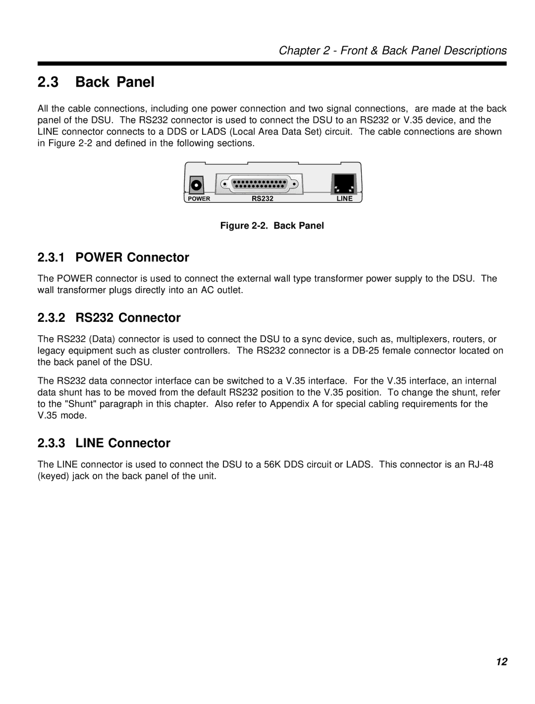
All the cable connections, including one power connection and two signal connections, are made at the back panel of the DSU. The RS232 connector is used to connect the DSU to an RS232 or V.35 device, and the LINE connector connects to a DDS or LADS (Local Area Data Set) circuit. The cable connections are shown in Figure
| RS232 |
|
|
|
POWER | LINE | |||
Figure 2-2. Back Panel
2.3.1 POWER Connector
The POWER connector is used to connect the external wall type transformer power supply to the DSU. The wall transformer plugs directly into an AC outlet.
2.3.2 RS232 Connector
The RS232 (Data) connector is used to connect the DSU to a sync device, such as, multiplexers, routers, or legacy equipment such as cluster controllers. The RS232 connector is a
The RS232 data connector interface can be switched to a V.35 interface. For the V.35 interface, an internal data shunt has to be moved from the default RS232 position to the V.35 position. To change the shunt, refer to the "Shunt" paragraph in this chapter. Also refer to Appendix A for special cabling requirements for the V.35 mode.
2.3.3 LINE Connector
The LINE connector is used to connect the DSU to a 56K DDS circuit or LADS. This connector is an
12