Chapter 3 - Unpacking & Setup
3.5V.35 Shunt
Either
CAUTION : This procedure requires opening the unit. Like most products of this type, this product contains components that are sensitive to static and static discharge. Use your best efforts to avoid static discharge when contacting the components inside this unit.
WARNING: Always disconnect the power cord before opening the enclosure to avoid any chance of electric shock.
1.Unplug the power cord.
2.The enclosure consists of two halves. Using a Phillips screwdriver, remove the two screws from the bottom of the unit. Remove the top half.
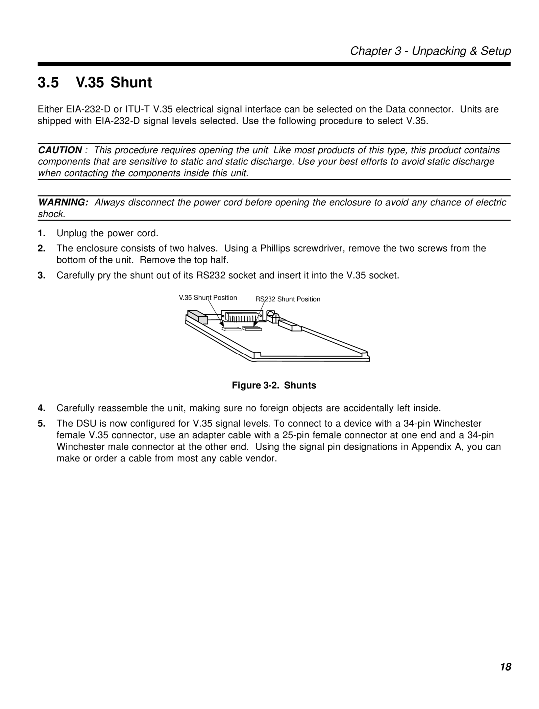
3.Carefully pry the shunt out of its RS232 socket and insert it into the V.35 socket.
V.35 Shunt Position | RS232 Shunt Position | |||||||
|
|
|
|
|
|
|
|
|
|
|
|
|
|
|
|
|
|
Figure 3-2. Shunts
4.Carefully reassemble the unit, making sure no foreign objects are accidentally left inside.
5.The DSU is now configured for V.35 signal levels. To connect to a device with a
18