Appendix
DB25S Connector with V.35 Interface
13 | 12 | 11 | 10 | 9 | 8 | 7 | 6 | 5 | 4 | 3 | 2 | 1 |
25 24 23 22 21 20 19 18 17 16 15 14
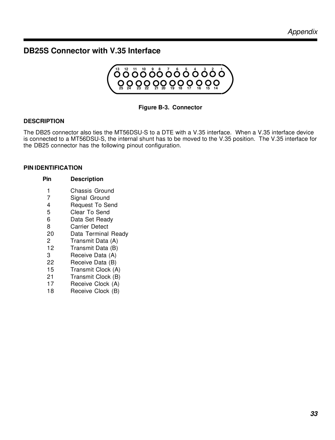
Figure B-3. Connector
DESCRIPTION
The DB25 connector also ties the
PIN IDENTIFICATION
Pin Description
1Chassis Ground
7Signal Ground
4Request To Send
5Clear To Send
6Data Set Ready
8Carrier Detect
20Data Terminal Ready
2Transmit Data (A)
12Transmit Data (B)
3Receive Data (A)
22Receive Data (B)
15Transmit Clock (A)
21Transmit Clock (B)
17Receive Clock (A)
18Receive Clock (B)
33