Chapter 3 - Unpacking & Setup
3.4Setup
Perform the following procedure to connect your cables and, if necessary, change to V.35 signaling on the data port.
1.If the DTE device has a V.35 interface, the internal shunt must be moved to the V.35 position and a V.35 adapter cable must be connected to the data connector (labeled “RS232”). Refer toV.35 Shunt for procedures on moving the shunt to the V.35 position. Refer to Appendix A for cable details.
If the DTE device has an
|
|
|
|
|
|
| RS232 |
|
|
|
|
| |
POWER |
|
|
|
| LINE |
| |||||||
|
|
|
|
|
|
|
|
|
|
|
|
|
|
|
|
|
|
|
|
|
|
|
|
|
|
|
|
|
|
|
|
|
|
|
|
|
|
|
|
|
|
|
|
|
|
|
|
|
|
|
|
|
|
|
|
|
|
|
|
|
|
|
|
|
|
|
|
|
|
|
|
|
|
|
|
|
|
|
|
|
|
|
|
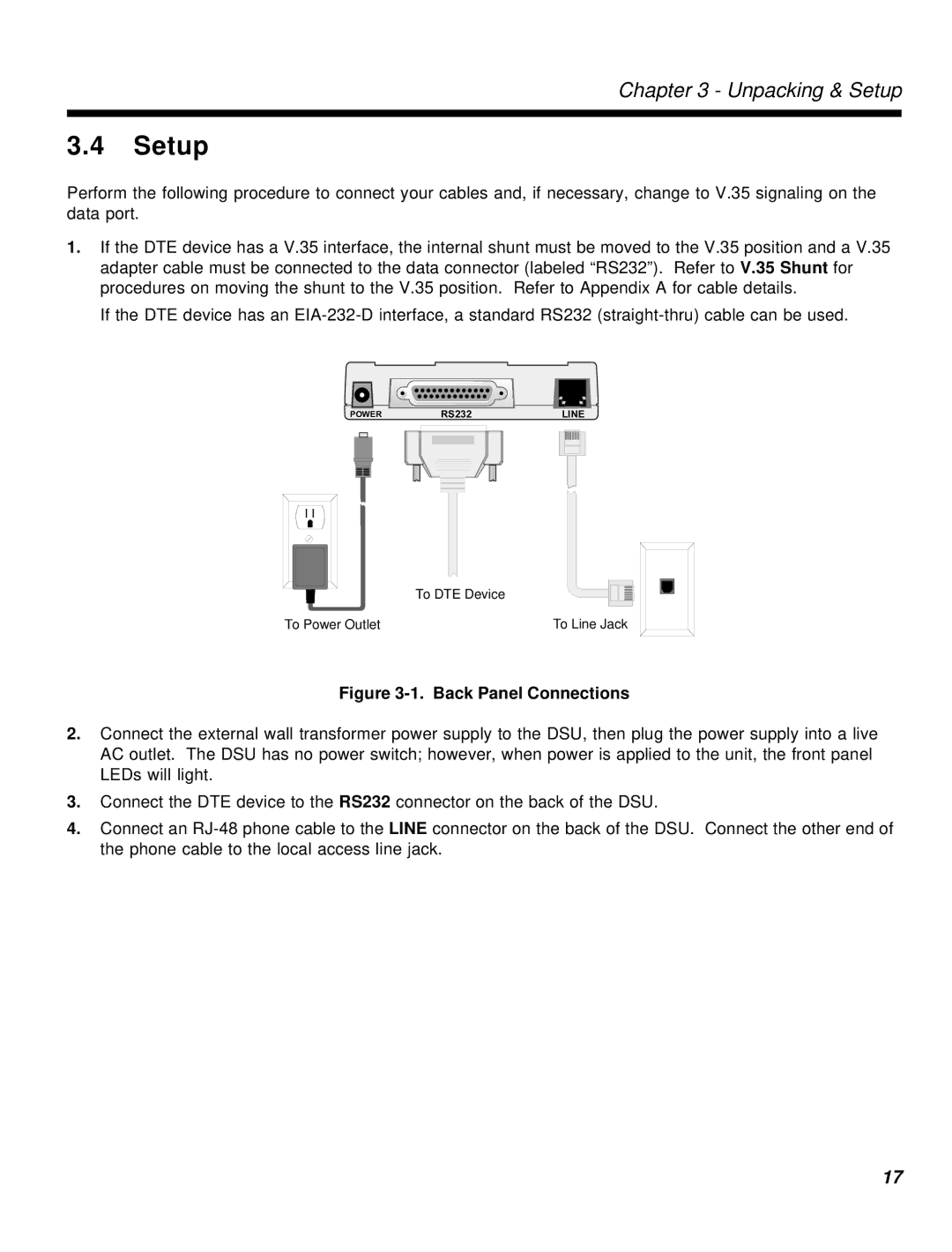
To DTE Device
To Power Outlet | To Line Jack |
Figure 3-1. Back Panel Connections
2.Connect the external wall transformer power supply to the DSU, then plug the power supply into a live AC outlet. The DSU has no power switch; however, when power is applied to the unit, the front panel LEDs will light.
3.Connect the DTE device to the RS232 connector on the back of the DSU.
4.Connect an
17