Cabling
Cabling Your MultiVOIP
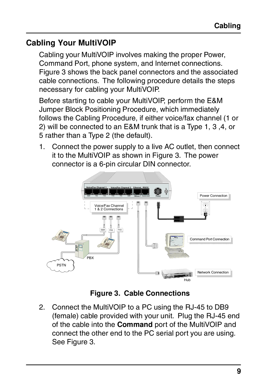
Cabling your MultiVOIP involves making the proper Power, Command Port, phone system, and Internet connections. Figure 3 shows the back panel connectors and the associated cable connections. The following procedure details the steps necessary for cabling your MultiVOIP.
Before starting to cable your MultiVOIP, perform the E&M Jumper Block Positioning Procedure, which immediately follows the Cabling Procedure, if either voice/fax channel (1 or
2)will be connected to an E&M trunk that is a Type 1, 3 ,4, or 5 rather than a Type 2 (the default).
1.Connect the power supply to a live AC outlet, then connect it to the MultiVOIP as shown in Figure 3. The power connector is a
Voice/Fax Channel 1 | Voice/Fax Channel 2 | Ethernet RS232 | 1 | ||||
|
|
|
|
|
|
| |
E&M | FXS | FXO |
|
|
| 0 | |
FXO | FXS | E&M | Power | ||||
Voice/Fax Channel
1 & 2 Connections
E&M ![]()
![]() FXS
FXS ![]()
![]() FXO
FXO
PBX
PSTN
Power Connection
Command Port Connection
Network Connection
Hub
Figure 3. Cable Connections
2.Connect the MultiVOIP to a PC using the
9