ASSEMBLY INSTRUCTIONS/OPERATIONS
OR EXTENSION CORD BEFORE PERFORMING ANY MAINTENANCE TO THE FLOOR PLANER. RECONNECT THE SPARK PLUG BEFORE RESTARTING THE ENGINE. IF ELECTRIC MOTOR EQUIPPED, TURN THE ON/OFF SWITCH TO THE OFF POSITION BEFORE RECONNECTING THE EXTENSION CORD. IMPROPER PROCEDURES CAN RESULT IN PROPERTY DAMAGE AND/OR PERSONAL INJURY.
CHECKING
Proper
Tools Required:
1 each, 16 inch minimum length straightedge.
1each, 10 lbs minimum capacity, tension scale or belt tension tool.
1)If the Floor Planer is powered by an engine, disconnect the spark plug wire. If powered by an electric motor, disconnect the extension cord or Floor Planer from the power source.
2)Position the Floor Planer on a suitable work bench with the
3)Using the 9/16 inch wrench, remove the belt guard from the main frame. Clean the inside of the belt guard with an appropriate solvent. Check for signs of wear and damage.
![]() CAUTION
CAUTION
Observe all applicable safety precautions for the solvent.
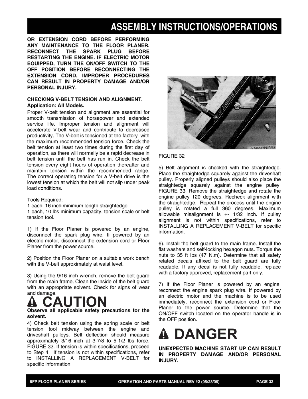
4)Check belt tension using the spring scale or belt tension tool midway between the engine and driveshaft pulleys. Belt deflection should measure approximately 3/16 inch at
FIGURE 32
5)Belt alignment is checked with the straightedge. Place the straightedge squarely against the driveshaft pulley. Properly aligned pulleys should also place the straightedge squarely against the engine pulley. FIGURE 33. Remove the straightedge and rotate the engine pulley 120 degrees. Recheck alignment with the straightedge. Repeat the process until the engine pulley is rotated a full 360 degrees. Maximum allowable misalignment is +- 1/32 inch. If pulley alignment is not within specifications, refer to INSTALLING A REPLACEMENT
6). Install the belt guard to the main frame. Install the flat washers and
7)If the Floor Planer is powered by an engine, reconnect the engine spark plug wire. If powered by an electric motor and the machine is to be used immediately, reconnect the extension cord or Floor Planer to the power source. Determine that the ON/OFF switch located on the operator handle is in the OFF position.
![]() DANGER
DANGER
UNEXPECTED MACHINE START UP CAN RESULT IN PROPERTY DAMAGE AND/OR PERSONAL INJURY.
8FP FLOOR PLANER SERIES | OPERATION AND PARTS MANUAL REV #2 (05/28/09) | PAGE 32 |
|
|
|