ASSEMBLY INSTRUCTIONS/OPERATIONS
4)Using the 1/2 inch wrenches, loosen the engine/electric motor attachment capscrews, and slide the engine/electric motor toward the front of the main frame. FIGURE 34.
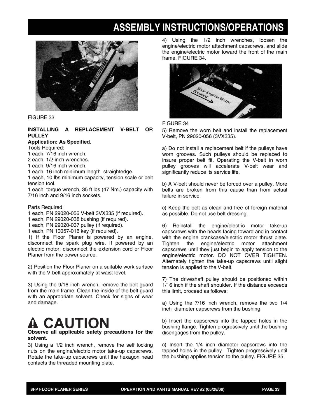
FIGURE 33
INSTALLING A REPLACEMENT V-BELT OR
PULLEY
Application: As Specified.
Tools Required:
1each, 7/16 inch wrench.
2each, 1/2 inch wrenches.
1each, 9/16 inch wrench.
1each, 16 inch minimum length straightedge.
1each, 10 lbs minimum capacity, tension scale or belt tension tool.
1each, torque wrench, 35 ft lbs (47 Nm.) capacity with 7/16 inch and 9/16 inch sockets.
Parts Required:
1each, PN
1each, PN
1each, PN
1each, PN
1) If the Floor Planer is powered by an engine, disconnect the spark plug wire. If powered by an electric motor, disconnect the extension cord or Floor Planer from the power source.
2)Position the Floor Planer on a suitable work surface with the
3)Using the 9/16 inch wrench, remove the belt guard from the main frame. Clean the inside of the belt guard with an appropriate solvent. Check for signs of wear and damage.
![]() CAUTION
CAUTION
Observe all applicable safety precautions for the solvent.
3)Using a 1/2 inch wrench, remove the self locking nuts on the engine/electric motor
FIGURE 34
5)Remove the worn belt and install the replacement
a) Do not install a replacement belt if the pulleys have worn grooves. Such pulleys should be replaced to insure proper belt fit. Operating the
b)A
c)Keep the belt as clean and free of foreign material as possible. Do not use belt dressing.
6)Reinstall the engine/electric motor
7)The driveshaft pulley should be positioned within 1/16 inch if the shaft shoulder. If the distance exceeds this limit, proceed as follows:
a) Using the 7/16 inch wrench, remove the two 1/4 inch diameter capscrews from the bushing.
b)Insert the capscrews into the tapped holes in the bushing flange. Tighten progressively until the bushing disengages from the pulley.
c)Insert the 1/4 inch diameter capscrews into the tapped holes in the pulley. Tighten progressively until the bushing applies tension to the pulley. FIGURE 35.
8FP FLOOR PLANER SERIES | OPERATION AND PARTS MANUAL REV #2 (05/28/09) | PAGE 33 |
|
|
|