ASSEMBLY INSTRUCTIONS/OPERATIONS
ALIGNING THE CASTER WHEELS.
Application: All Models.
Tools Required:
1each, 16 inch minimum length straightedge
2each, 3/4 inch wrenches
1each, torque wrench, 85 ft lbs (115 Nm.) capacity with 3/4 inch socket.
1each, 6 inch scale.
Proper front and rear caster wheel alignment is essential to produce an even cutting action by the flails. With use, caster bearings and axles will eventually wear. Excessive caster bearing and axle wear can contribute to an uneven cutting action. In addition, a sharp blow delivered to the Floor Planer (eg; being dropped to the surface from off a truck) can also affect the caster wheel alignment.
Caster wheels are aligned during assembly with the use of a specially designed alignment jig. However, satisfactory results can also be achieved in the field by following steps:
1)Position the Floor Planer on a suitable work surface. If the Floor Planer is powered by an engine and the engine is not to be removed, fuel and oil must be first drained from the fuel tank and crankcase. If powered by an electric motor, disconnect the extension cord or Floor Planer from the power source. The normal position for aligning the caster wheels is with the main frame perpendicular to the work surface. Support the unit with proper blocking.
2)Shim washers of .015 inch (.381 mm) thickness are sometimes utilized when fastening the front axle assembly to the main frame. Install washers as required. FIGURE 50. The fasteners that attach the front axle assembly should be tightened until slight tension is applied. Always position the 1/2 inch flat washers against the slots provided in the axle assembly.
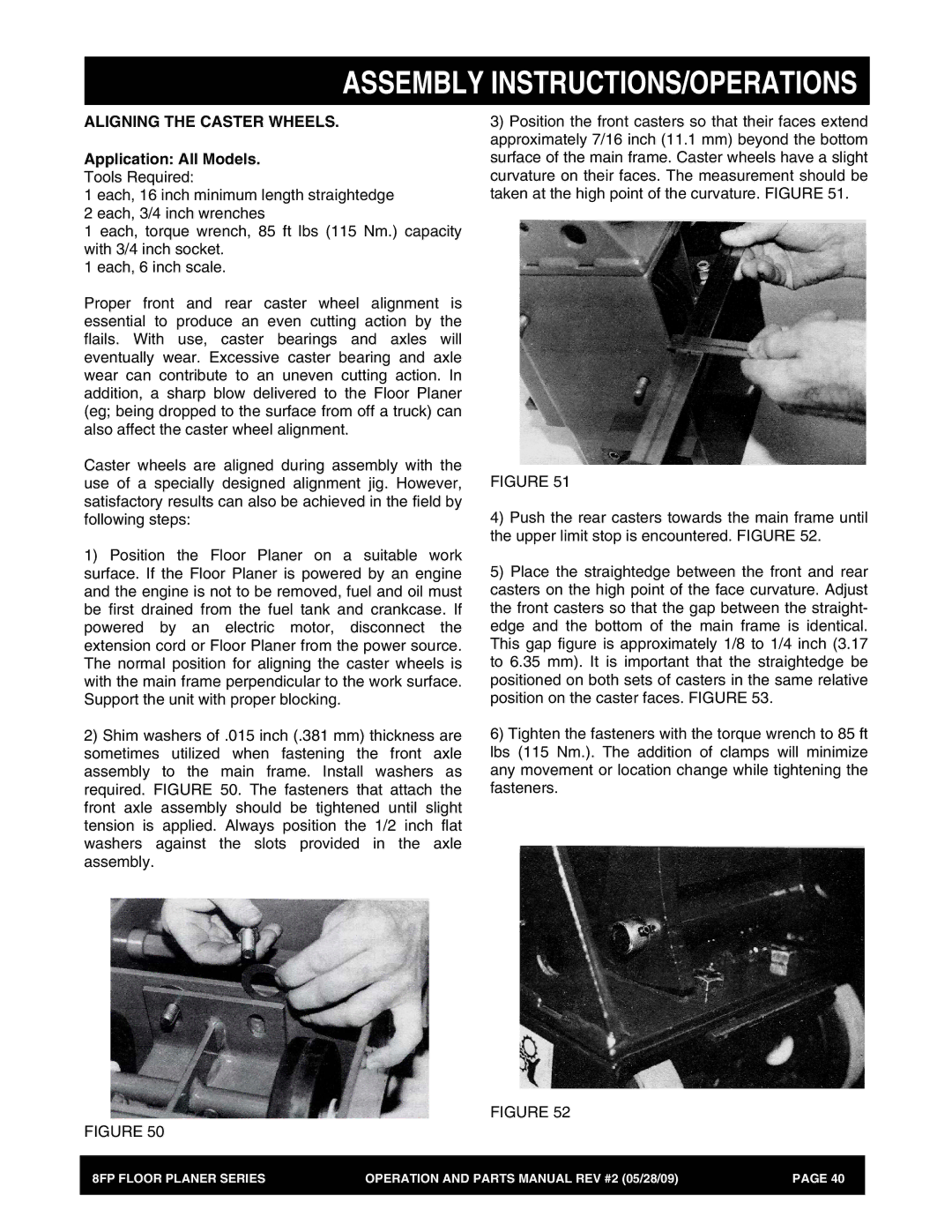
3)Position the front casters so that their faces extend approximately 7/16 inch (11.1 mm) beyond the bottom surface of the main frame. Caster wheels have a slight curvature on their faces. The measurement should be taken at the high point of the curvature. FIGURE 51.
FIGURE 51
4)Push the rear casters towards the main frame until the upper limit stop is encountered. FIGURE 52.
5)Place the straightedge between the front and rear casters on the high point of the face curvature. Adjust the front casters so that the gap between the straight- edge and the bottom of the main frame is identical. This gap figure is approximately 1/8 to 1/4 inch (3.17 to 6.35 mm). It is important that the straightedge be positioned on both sets of casters in the same relative position on the caster faces. FIGURE 53.
6)Tighten the fasteners with the torque wrench to 85 ft lbs (115 Nm.). The addition of clamps will minimize any movement or location change while tightening the fasteners.
FIGURE 52
FIGURE 50
8FP FLOOR PLANER SERIES | OPERATION AND PARTS MANUAL REV #2 (05/28/09) | PAGE 40 |
|
|
|