
DCA-300SSK specifications
The Multiquip DCA-300SSK is a powerful and versatile silent diesel generator designed to meet the demands of various applications, from construction sites to outdoor events. With its robust features and advanced technologies, this generator ensures reliability and efficiency in power generation.One of the standout features of the DCA-300SSK is its impressive power output capability. With a maximum capacity of 300 kVA, it can support multiple tools and equipment simultaneously, making it ideal for construction projects, emergency backup, and rental services. Its diesel engine, known for its durability, provides a consistent power supply while being fuel-efficient.
The DCA-300SSK is also notable for its sound attenuation technology. Equipped with a specialized enclosure, this generator operates at a reduced noise level, making it suitable for noise-sensitive environments. This feature is particularly beneficial in urban settings or during nighttime operations where excessive noise could be disruptive.
Safety is paramount in any power generation equipment, and the DCA-300SSK integrates various safety features to protect both the operator and the machine. It includes an automatic shutdown function for low oil pressure and high coolant temperature, ensuring the engine is safeguarded against potential damage. Additionally, the generator is equipped with circuit breakers to prevent electrical overloads, enhancing overall operational safety.
Portability is another key characteristic of the DCA-300SSK. The unit is mounted on a heavy-duty frame with integrated lifting and transport provisions, enabling easy relocation. This feature is particularly advantageous for contractors who need to move the generator frequently from one job site to another.
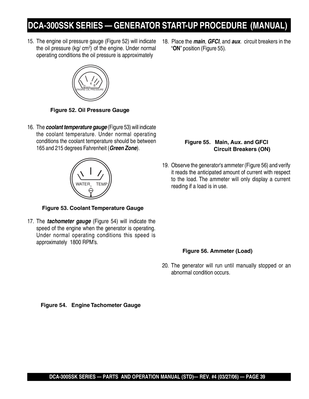
The generator also features a user-friendly control panel, providing operators with easy access to monitoring essential parameters such as voltage, frequency, and operational hours. This design ensures that users can maintain optimal performance while minimizing downtime.
With its reliable performance, innovative technology, and user-centric design, the Multiquip DCA-300SSK stands out as a top choice for anyone seeking a dependable diesel generator solution. Whether for emergency backup power or heavy-duty usage, the DCA-300SSK delivers efficiency and peace of mind in power generation.