MultiFRAD
Front Panel Description
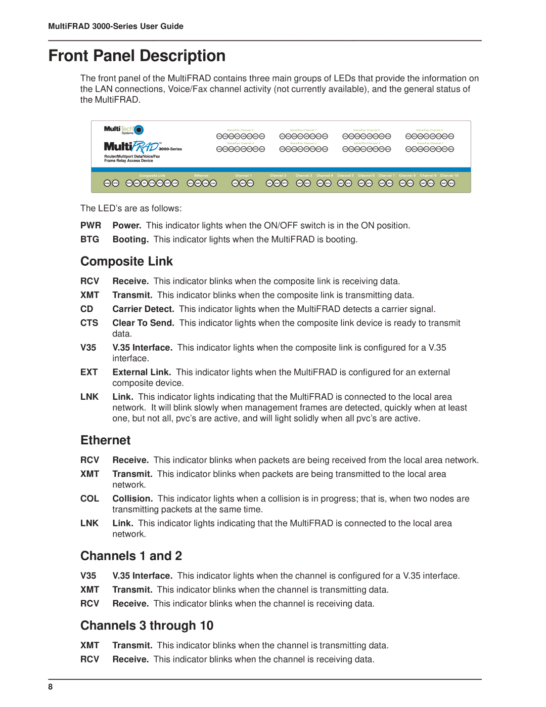
The front panel of the MultiFRAD contains three main groups of LEDs that provide the information on the LAN connections, Voice/Fax channel activity (not currently available), and the general status of the MultiFRAD.
|
| Voice/Fax Channel 8 |
|
|
|
| Voice/Fax Channel 7 |
|
|
|
| Voice/Fax Channel 6 |
|
|
|
| Voice/Fax Channel 5 |
|
| ||||||||||||
FXS | FXD | E&M | FAX | XMT | RCV | XSG | RSG | FXS | FXD | E&M | FAX | XMT | RCV | XSG | RSG | FXS | FXD | E&M | FAX | XMT | RCV | XSG | RSG | FXS | FXD | E&M | FAX | XMT | RCV | XSG | RSG |
|
| Voice/Fax Channel 4 |
|
|
|
| Voice/Fax Channel 3 |
|
|
|
| Voice/Fax Channel 2 |
|
|
| Voice/Fax Channel 1 |
| ||||||||||||||
FXS | FXD | E&M | FAX | XMT | RCV | XSG | RSG | FXS | FXD | E&M | FAX | XMT | RCV | XSG | RSG | FXS | FXD | E&M | FAX | XMT | RCV | XSG | RSG | FXS | FXD | E&M | FAX | XMT | RCV | XSG | RSG |
| Composite Link | Ethernet | Channel 1 | Channel 2 | Channel 3 | Channel 4 | Channel 5 | Channel 6 | Channel 7 | Channel 8 | Channel 9 | Channel 10 |
PWR BTG | RCV XMT CD CTS V35 EXT LNK | RCV XMT COL LNK | V35 XMT RCV | V35 XMT RCV | XMT RCV | XMT RCV | XMT RCV | XMT RCV | XMT RCV | XMT RCV | XMT RCV | XMT RCV |
The LED’s are as follows:
PWR | Power. This indicator lights when the ON/OFF switch is in the ON position. |
BTG | Booting. This indicator lights when the MultiFRAD is booting. |
Composite Link
RCV | Receive. This indicator blinks when the composite link is receiving data. |
XMT | Transmit. This indicator blinks when the composite link is transmitting data. |
CD | Carrier Detect. This indicator lights when the MultiFRAD detects a carrier signal. |
CTS | Clear To Send. This indicator lights when the composite link device is ready to transmit |
| data. |
V35 | V.35 Interface. This indicator lights when the composite link is configured for a V.35 |
| interface. |
EXT | External Link. This indicator lights when the MultiFRAD is configured for an external |
| composite device. |
LNK | Link. This indicator lights indicating that the MultiFRAD is connected to the local area |
| network. It will blink slowly when management frames are detected, quickly when at least |
| one, but not all, pvc’s are active, and will light solidly when all pvc’s are active. |
Ethernet
RCV | Receive. This indicator blinks when packets are being received from the local area network. |
XMT | Transmit. This indicator blinks when packets are being transmitted to the local area |
| network. |
COL | Collision. This indicator lights when a collision is in progress; that is, when two nodes are |
| transmitting packets at the same time. |
LNK | Link. This indicator lights indicating that the MultiFRAD is connected to the local area |
| network. |
Channels 1 and 2
V35 | V.35 Interface. This indicator lights when the channel is configured for a V.35 interface. |
XMT | Transmit. This indicator blinks when the channel is transmitting data. |
RCV | Receive. This indicator blinks when the channel is receiving data. |
Channels 3 through 10
XMT | Transmit. This indicator blinks when the channel is transmitting data. |
RCV | Receive. This indicator blinks when the channel is receiving data. |
8
