GDS60-N, GS60-N, GDS60-P, GS60-P specifications
Napoleon Fireplaces offers an impressive line of gas fireplaces, including the GDS60-N, GS60-N, GS60-P, and GDS60-P models, which represent the pinnacle of style, efficiency, and technology in modern heating solutions. These fireplaces are designed to enhance the comfort of your living space while ensuring an inviting atmosphere.One of the standout features of the GDS60-N and GS60-N models is the unique Design and Style Series, which provides flexibility in customization. Homeowners can choose from a variety of finishes, including classic and contemporary styles, to seamlessly integrate the fireplace into their existing décor. The clean lines and elegant design make these units a focal point in any room.
Both models prioritize efficiency, boasting impressive heating capabilities that can warm spaces of significant size. They utilize advanced combustion technology, ensuring that heat is distributed evenly while maximizing fuel efficiency. The GDS60-P and GS60-P models offer similar features but come with a premium touch, providing enhanced aesthetics with their panoramic viewing area that showcases a mesmerizing flame display.
The burner system in these fireplaces is engineered for consistent performance, allowing users to enjoy the beauty of flickering flames with minimal maintenance. Innovative features such as the exclusive PHAZER log set provide a realistic fire effect, further enhancing the ambiance and visual appeal of the fireplace.
Additionally, Napoleon fireplaces incorporate top-tier safety measures, including an automatic shut-off feature, which ensures peace of mind for users. The intuitive remote control system enables easy temperature adjustments and flame settings, allowing for personalized comfort at the touch of a button.
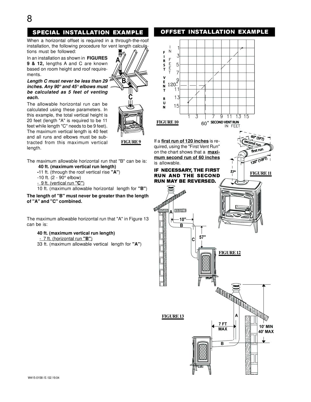
Another notable characteristic is the easy installation process. These units are designed for both direct venting and conventional venting, offering versatility that caters to various home layouts. The manufacturers have placed a strong emphasis on craftsmanship, ensuring that each unit not only performs optimally but also lasts for years to come.
In conclusion, the Napoleon Fireplaces GDS60-N, GS60-N, GS60-P, and GDS60-P models epitomize the perfect fusion of technology, efficiency, and design. Homeowners looking for a reliable heating solution that doesn't compromise on style will find these gas fireplaces to be an excellent choice. With their captivating aesthetics, advanced features, and superior safety specifications, Napoleon continues to set a high standard in the fireplace industry.

