NTI NODEMUX SERIES UNIVERSAL KVM SWITCH
PLEASE NOTE: It is necessary to configure a Sun CPU such that the Sleep Mode is not enabled. If a Sun CPU goes into sleep mode either automatically or manually, the user must reboot the Sun CPU in order to resume use of the Sun CPU.
To disable the Sleep Mode, perform the following steps:
1.Select "Power Manager"
2.Look for "Device Idle Time Before Power Saving Starts"
3.Select "Always ON"
4.Look for "Override Device Idle Time For:"
5.Make sure neither "Monitors" nor "Disks" are selected
RS232 CONTROL
(Optional)
RS232 Connections and Configuration
Remote Connection
RearViewofST-2U-RS
RS232
OFF 12345678 ON
VIDEO2 VIDEO1 MONITOR
CPU2 CPU1 USER
6 | 5 | 6 | 5 | 6 | 5 |
4 | 3 | 4 | 3 | 4 | 3 |
2 | 1 | 2 | 1 | 2 | 1 |
PWR
The RS232 Interface is designed to meet the RS232C standard and can be controlled from any host CPU or other controller with an RS232 communications port. A straight through
Baud Rate
The baud rate of the host CPU can be changed by using the menus in the RMTEST program (see "RS232 Interface Test Program" below). The desired baud rate of 9600, 2400, 1200, or 300 may be set. A data protocol of 8 data bits, no parity, and 1 stop bit is used for communications. The baud rate of the KEEMUX is configured using dipswitches (see Fig. 17).
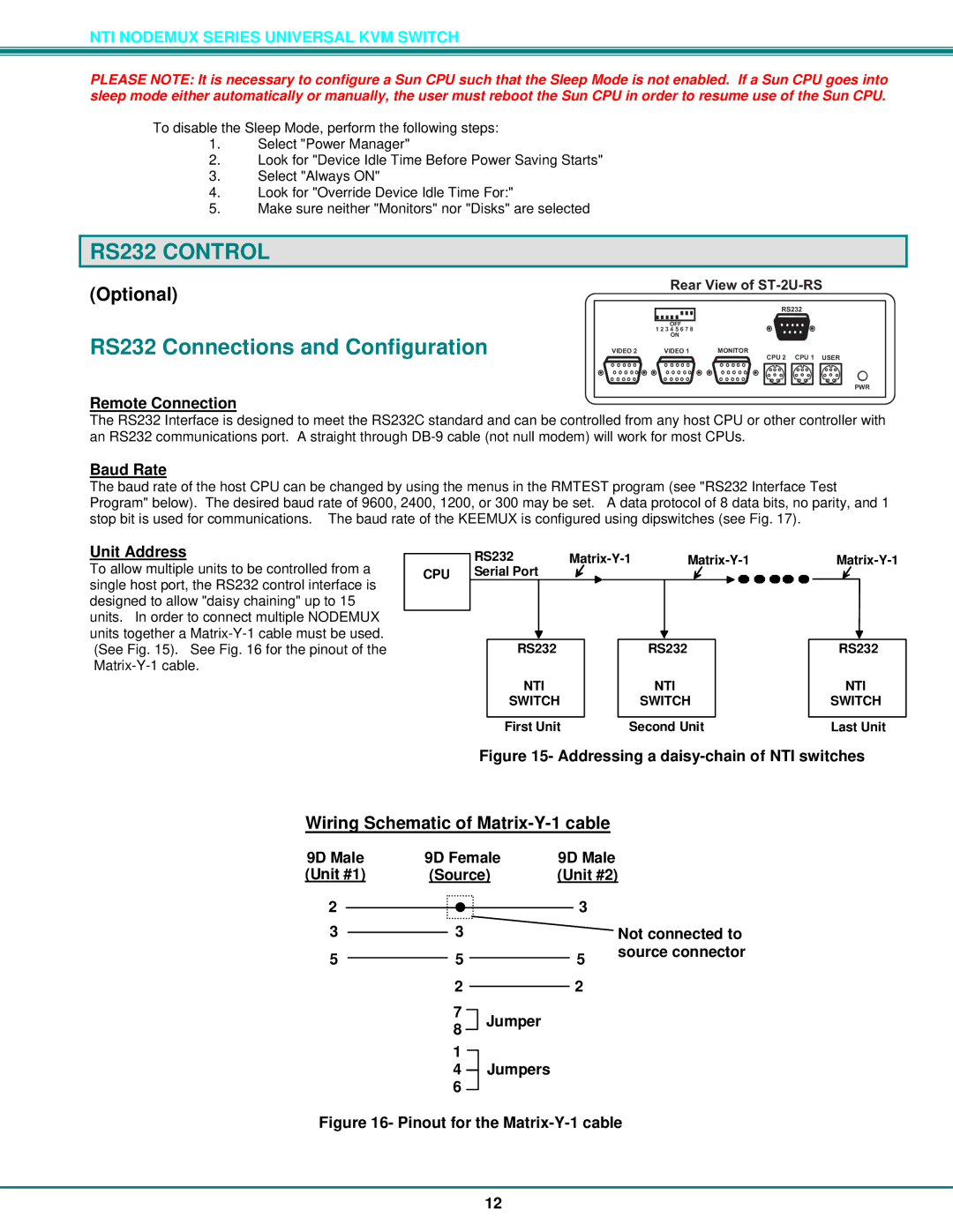
Unit Address | RS232 | ||||
To allow multiple units to be controlled from a | |||||
CPU Serial Port |
|
|
| ||
single host port, the RS232 control interface is |
|
|
|
| |
designed to allow "daisy chaining" up to 15 |
|
|
|
| |
units. In order to connect multiple NODEMUX |
|
|
|
| |
units together a | RS232 |
| RS232 | RS232 | |
(See Fig. 15). See Fig. 16 for the pinout of the |
| ||||
|
|
|
| ||
| NTI |
| NTI | NTI | |
| SWITCH |
| SWITCH | SWITCH | |
| First Unit | Second Unit | Last Unit | ||
Figure 15- Addressing a daisy-chain of NTI switches
Wiring Schematic of Matrix-Y-1 cable
9D Male | 9D Female | 9D Male |
|
(Unit #1) | (Source) | (Unit #2) | |
2 |
| 3 |
|
3 | 3 |
| Not connected to |
5 | 5 | 5 | source connector |
| |||
22
7
8 Jumper
1
4Jumpers
Figure 16- Pinout for the Matrix-Y-1 cable
12