FRONT AND REAR PANEL
Front panel
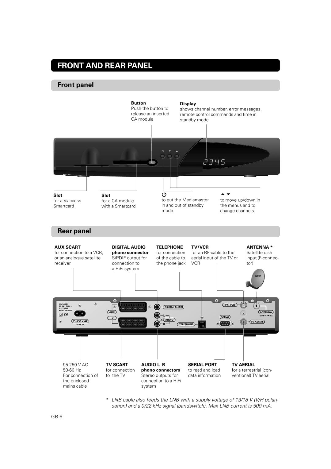
Button
Push the button to release an inserted CA module
Display
shows channel number, error messages, remote control commands and time in standby mode
Slot | Slot |
for a Viaccess | for a CA module |
Smartcard | with a Smartcard |
to put the Mediamaster in and out of standby mode
to move up/down in the menus and to change channels.
Rear panel
AUX SCART | DIGITAL AUDIO | TELEPHONE | TV/VCR | ANTENNA * | |||||||||||
for connection to a VCR, | phono connector | for connection | for an | Satellite dish | |||||||||||
or an analogue satellite | S/PDIF output for | of the cable to | aerial input of the TV or | input | |||||||||||
receiver | connection to | the phone jack | VCR |
|
| tor) | |||||||||
|
|
| a HiFi system |
|
|
|
|
|
|
|
|
|
| ||
|
|
|
|
|
|
|
|
|
|
|
|
| |||
|
|
|
|
|
|
|
|
|
|
|
|
|
|
|
|
|
|
|
|
|
|
|
|
|
|
|
|
|
|
|
|
|
|
|
|
|
|
|
|
|
|
|
|
|
|
|
|
|
|
|
|
|
|
|
|
|
|
|
|
|
|
|
|
|
|
|
|
|
|
|
|
|
|
|
|
|
|
|
|
|
|
|
|
|
|
|
|
|
|
|
|
|
|
|
|
|
|
|
|
|
|
|
|
|
|
|
|
|
|
|
|
|
|
|
|
|
|
|
|
|
|
|
|
|
|
|
|
|
|
|
|
|
|
|
|
|
|
|
|
|
|
|
|
|
|
|
|
|
|
|
|
|
|
|
|
|
|
|
|
|
|
|
|
|
|
|
|
|
|
|
|
|
|
|
|
TV SCART | AUDIO L R | SERIAL PORT | TV AERIAL | |
for connection | phono connectors | to read and load | for a terrestrial (con- | |
For connection of | to the TV | Stereo outputs for | data information | ventional) TV aerial |
the enclosed |
| connection to a HiFi |
|
|
mains cable |
| system |
|
|
*LNB cable also feeds the LNB with a supply voltage of 13/18 V (V/H polari- sation) and a 0/22 kHz signal (bandswitch). Max LNB current is 500 mA.
GB 6