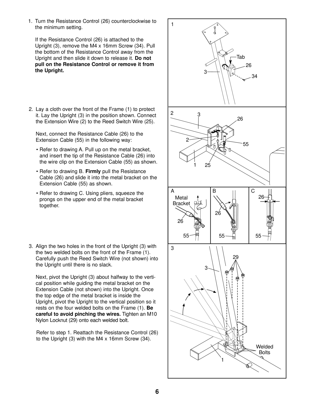
1. Turn the Resistance Control (26) counterclockwise to | 1 |
|
| ||
the minimum setting. |
|
|
|
| |
|
|
|
|
| |
If the Resistance Control (26) is attached to the |
|
|
| ||
Upright (3), remove the M4 x 16mm Screw (34). Pull |
|
|
| ||
the bottom of the Resistance Control away from the |
|
| Tab | ||
Upright and then slide it down to release it. | Do not |
| |||
pull on the Resistance Control or remove it from |
|
| 26 | ||
the Upright. |
|
|
| 3 | 34 |
|
|
|
| ||
|
|
|
|
| |
2. Lay a cloth over the front of the Frame (1) to protect | 2 | 3 |
| ||
it. Lay the Upright (3) in the position shown. Connect | 26 | ||||
the Extension Wire (2) to the Reed Switch Wire (25). |
|
| |||
|
|
| |||
Next, connect the Resistance Cable (26) to the |
|
|
| ||
Extension Cable (55) in the following way: | 2 |
| 55 | ||
• Refer to drawing A. Pull up on the metal bracket, |
|
| |||
|
|
| |||
and insert the tip of the Resistance Cable (26) into |
|
|
| ||
the wire clip on the Extension Cable (55) as shown. | 1 | 25 |
| ||
|
|
|
| ||
• Refer to drawing B. | Firmly | pull the Resistance |
|
|
|
Cable (26) and slide it into the metal bracket on the |
|
|
| ||
Extension Cable (55) as shown. |
|
|
|
| |
• Refer to drawing C. Using pliers, squeeze the | A | B | C | ||
Metal |
| 26 | |||
prongs on the upper end of the metal bracket |
| ||||
Bracket |
|
| |||
together. |
|
|
|
| |
|
|
|
|
| |
|
|
|
| 26 |
|
|
|
| 26 |
|
|
|
|
| 55 | 55 | 55 |
3. Align the two holes in the front of the Upright (3) with | 3 |
|
| ||
the two welded bolts on the front of the Frame (1). |
|
| |||
|
| 29 | |||
Carefully push the Reed Switch Wire (not shown) into |
|
| |||
the Upright until there is no slack. |
|
| 3 |
| |
|
|
|
|
| |
Next, pivot the Upright (3) about halfway to the verti- |
|
|
| ||
cal position while guiding the metal bracket on the |
|
|
| ||
Extension Cable (not shown) into the Upright. Once |
|
|
| ||
the top edge of the metal bracket is inside the |
|
|
| ||
Upright, pivot the Upright to the vertical position so it |
|
|
| ||
rests on the four welded bolts on the Frame (1). | Be |
|
| ||
careful to avoid pinching the wires. | Tighten an M10 |
|
| ||
Nylon Locknut (29) onto each welded bolt. |
|
|
| ||
Refer to step 1. Reattach the Resistance Control (26) |
|
|
| ||
to the Upright (3) with the M4 x 16mm Screw (34). |
|
|
| ||
|
|
|
|
| Welded |
|
|
|
|
| Bolts |
|
|
|
| 1 |
|
|
|
| 6 |
|
|
