INSTALLATION (Continued)
WARNING! NEVER EXCEED A TOTAL OF 15 NUTONE 25 OHM SPEAKERS ON THIS SYSTEM.
WARNING! NEVER USE STANDARD 8 OHM STEREO SPEAKERS ON THIS SYSTEM. USE ONLY NUTONE SPECIFIED SPEAKERS ON THIS MASTER.
MOUNTING THE TERMINAL BOARD
1.Remove and clean any drywall debris or dust from the
2.Refer to Figure 1. Locate the terminal board in the left rear section of the
3.Use four (4) Nº 6 x 3⁄8“ screws supplied to secure the terminal board to the
4.Make certain the lower
Make sure it is positioned between the screw and terminal board.
IMPORTANT | |
▲ | ▲ |
DO NOT APPLY POWER TO THE SYSTEM UNTIL ALL CONNECTIONS ARE COMPLETE AT THE MASTER AND REMOTE STATIONS.
FIGURE 1 |
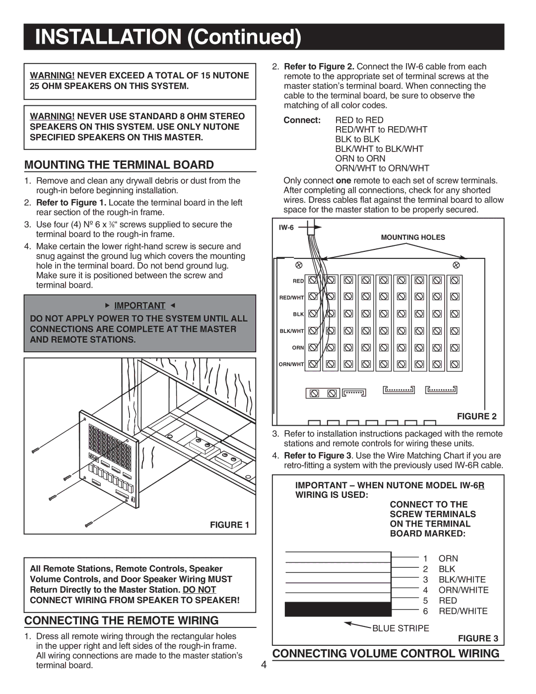
2.Refer to Figure 2. Connect the
Connect: RED to RED RED/WHT to RED/WHT BLK to BLK BLK/WHT to BLK/WHT ORN to ORN ORN/WHT to ORN/WHT
Only connect one remote to each set of screw terminals. After completing all connections, check for any shorted wires. Dress cables flat against the terminal board to allow space for the master station to be properly secured.
MOUNTING HOLES
RED |
RED/WHT |
BLK |
BLK/WHT |
ORN |
ORN/WHT |
FIGURE 2
3.Refer to installation instructions packaged with the remote stations and remote controls for wiring these units.
4.Refer to Figure 3. Use the Wire Matching Chart if you are
IMPORTANT – WHEN NUTONE MODEL
CONNECT TO THE
SCREW TERMINALS
ON THE TERMINAL
BOARD MARKED:
All Remote Stations, Remote Controls, Speaker Volume Controls, and Door Speaker Wiring MUST Return Directly to the Master Station. DO NOT CONNECT WIRING FROM SPEAKER TO SPEAKER!
CONNECTING THE REMOTE WIRING
1.Dress all remote wiring through the rectangular holes in the upper right and left sides of the
1 | ORN |
2 | BLK |
3 | BLK/WHITE |
4 | ORN/WHITE |
5 | RED |
6 | RED/WHITE |
![]() BLUE STRIPE
BLUE STRIPE
FIGURE 3
CONNECTING VOLUME CONTROL WIRING
4