INSTALLATION (Continued)
Model
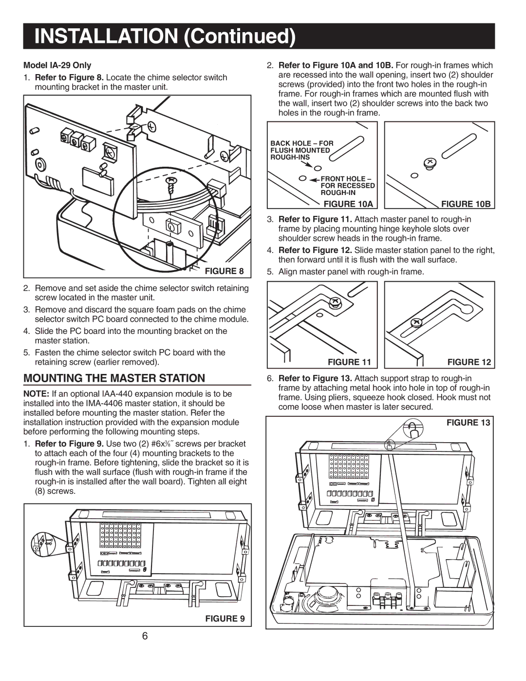
1.Refer to Figure 8. Locate the chime selector switch mounting bracket in the master unit.
2.Refer to Figure 10A and 10B. For
BACK HOLE – FOR
FLUSH MOUNTED
![]()
![]() FRONT HOLE –
FRONT HOLE –
FOR RECESSED
FIGURE 10A
FIGURE 10B |
2.Remove and set aside the chime selector switch retaining screw located in the master unit.
3.Remove and discard the square foam pads on the chime selector switch PC board connected to the chime module.
4.Slide the PC board into the mounting bracket on the master station.
5.Fasten the chime selector switch PC board with the retaining screw (earlier removed).
MOUNTING THE MASTER STATION
NOTE: If an optional
1.Refer to Figure 9. Use two (2) #6x3⁄8˝ screws per bracket to attach each of the four (4) mounting brackets to the
(8) screws.
FIGURE 9 |
6 |
3.Refer to Figure 11. Attach master panel to
4.Refer to Figure 12. Slide master station panel to the right, then forward until it is flush with the wall surface.
5.Align master panel with
FIGURE 11 |
| FIGURE 12 |
6.Refer to Figure 13. Attach support strap to
FIGURE 13 |