INSTALLATION (Continued)
CONNECTING THE RADIO ANTENNA
1.Refer to Figure 18. Plug radio antenna (supplied with IR105
TAB |
FIGURE 18 |
NOTE: Any excess antenna cable should be located outside of
In most locations the antenna supplied with the
1.Refer to Figure 19. Move the auxiliary antenna selector switch to the AM position.
2.Connect 50 feet of 22 ga. insulated wire to the screw terminal marked AM ANTENNA.
3.Run the wire from the master station location to the attic. Fasten the insulated wire at one end of the attic; stretch the wire to its full length and fasten at the opposite end.
Fasten the insulated wire at several locations between ends to prevent sagging.
AM/FM |
AM ONLY |
AM ANTENNA |
FIGURE 19 |
CONNECTING THE OPTIONAL
CHIME MODULE
It is now time to connect the optional chime module that you earlier installed into the master station.
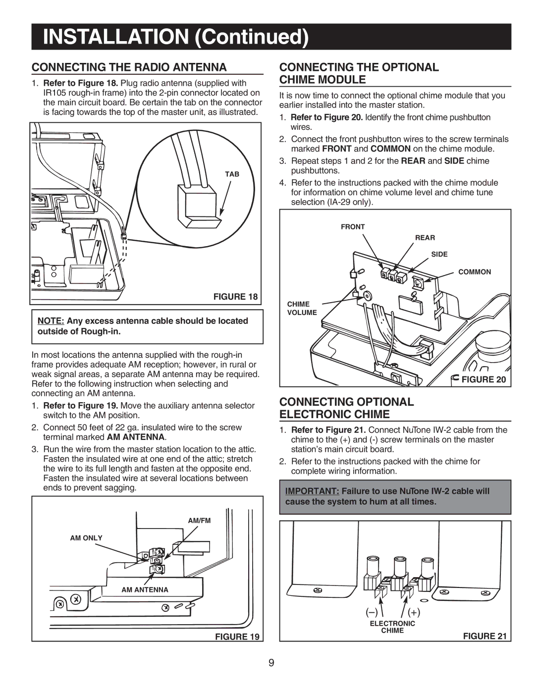
1.Refer to Figure 20. Identify the front chime pushbutton wires.
2.Connect the front pushbutton wires to the screw terminals marked FRONT and COMMON on the chime module.
3.Repeat steps 1 and 2 for the REAR and SIDE chime pushbuttons.
4.Refer to the instructions packed with the chime module for information on chime volume level and chime tune selection
FRONT
REAR
SIDE
COMMON
CHIME
VOLUME
FIGURE 20
CONNECTING OPTIONAL
ELECTRONIC CHIME
1.Refer to Figure 21. Connect NuTone
2.Refer to the instructions packed with the chime for complete wiring information.
IMPORTANT: Failure to use NuTone
![]()
![]() (+)
(+)
ELECTRONIC
CHIME
FIGURE 21
9