INSTALLATION (Continued)
MOUNTING AND CONNECTING OPTIONAL DOOR RELEASE PUSHBUTTON
You have previously prepared the master station for the optional release pushbutton.
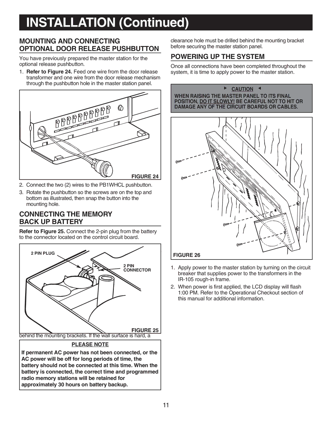
1.Refer to Figure 24. Feed one wire from the door release transformer and one wire from the door release mechanism through the pushbutton hole in the master station panel.
FIGURE 24 |
2.Connect the two (2) wires to the PB1WHCL pushbutton.
3.Rotate the pushbutton so the screws are on the top and bottom as illustrated, then snap the button into the mounting hole.
CONNECTING THE MEMORY
BACK UP BATTERY
Refer to Figure 25. Connect the
SECURING THE MASTER PANEL
2 PIN PLUG
1. Refer to Figure 26. Inspect all wiring connections to make sure they are complete and correct.
2.Make sure all antenna connections are secureCONNECTOR.
3.Dress all remote station wires![]() flat against the terminal board.
flat against the terminal board. ![]()
4.Position the master station panel over the
and align screw holes in master with mounting brackets.
Two (2) mountingbehind the CD Player door.
5.Secure the master station panel to the
NOTE: The mounting screws will pierce the wall surfaceFIGURE 25
behind the mounting brackets. If the wall surface is hard, a
PLEASE NOTE
clearance hole must be drilled behind the mounting bracket before securing the master station panel.
POWERING UP THE SYSTEM
Once all connections have been completed throughout the system, it is time to apply power to the master station.
▲ | CAUTION | ▲ |
|
|
WHEN RAISING THE MASTER PANEL TO ITS FINAL POSITION, DO IT SLOWLY! BE CAREFUL NOT TO HIT OR DAMAGE ANY OF THE CIRCUIT BOARDS OR CABLES.
FIGURE 26 |
1.Apply power to the master station by turning on the circuit breaker that supplies power to the transformers in the
2.When power is first applied, the LCD display will flash 1:00 PM. Refer to the Operational Checkout section of this manual for additional information.
If permanent AC power has not been connected, or the AC power will be off for long periods of time, the battery should not be connected at this time. When the battery is connected, the correct time and programmed radio memory stations will be retained for approximately 30 hours on battery backup.
11