Installing Essentia in Your Home
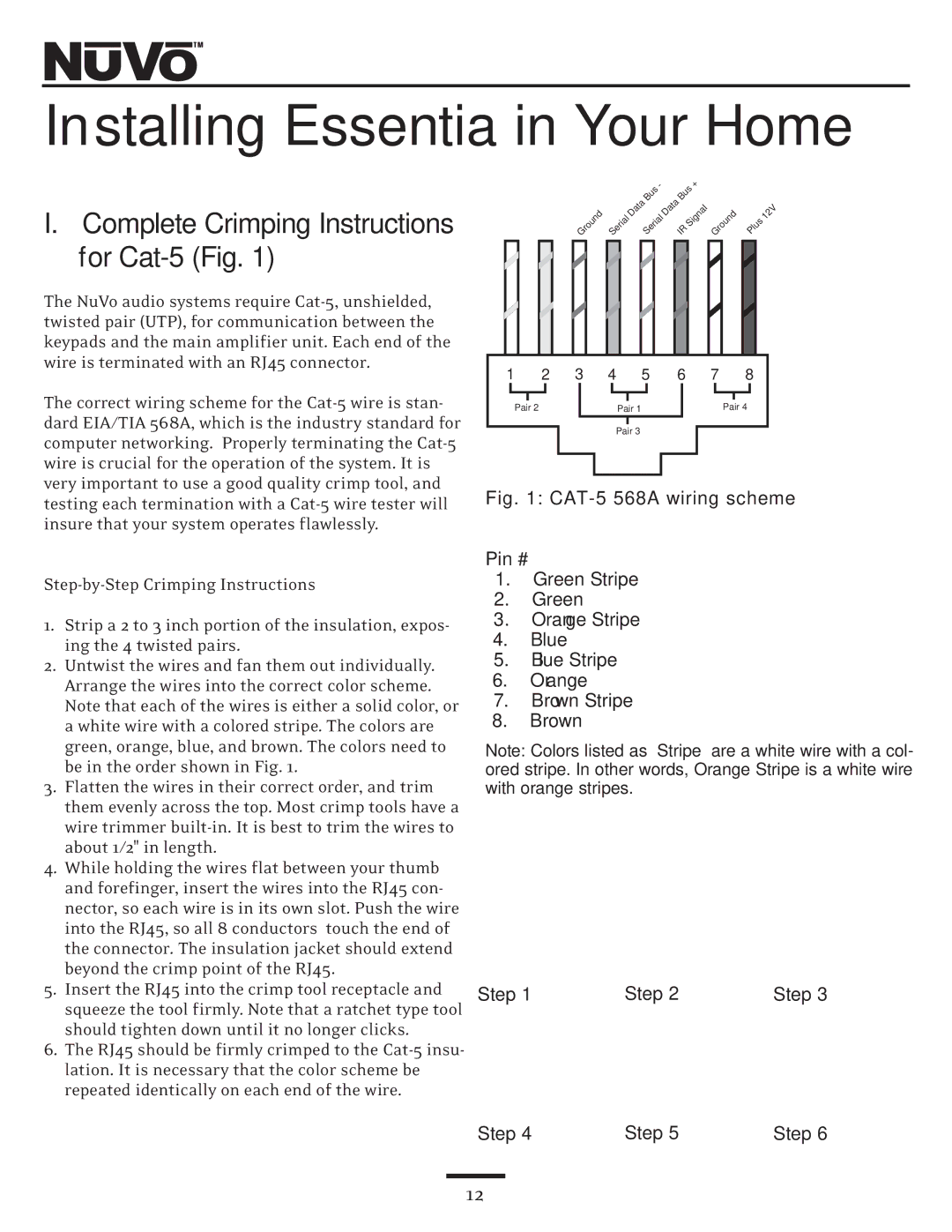
I.Complete Crimping Instructions for Cat-5 (Fig. 1)
The NuVo audio systems require
The correct wiring scheme for the
1.Strip a 2 to 3 inch portion of the insulation, expos- ing the 4 twisted pairs.
2.Untwist the wires and fan them out individually. Arrange the wires into the correct color scheme. Note that each of the wires is either a solid color, or a white wire with a colored stripe. The colors are green, orange, blue, and brown. The colors need to be in the order shown in Fig. 1.
3.Flatten the wires in their correct order, and trim them evenly across the top. Most crimp tools have a wire trimmer
4.While holding the wires flat between your thumb and forefinger, insert the wires into the RJ45 con- nector, so each wire is in its own slot. Push the wire into the RJ45, so all 8 conductors touch the end of the connector. The insulation jacket should extend beyond the crimp point of the RJ45.
5.Insert the RJ45 into the crimp tool receptacle and squeeze the tool firmly. Note that a ratchet type tool should tighten down until it no longer clicks.
6.The RJ45 should be firmly crimped to the
|
|
|
|
| - |
| Bus | + |
|
| |
|
|
|
| Data | Bus | Data |
|
|
| ||
|
| Ground | Serial | Serial |
| Signal Ground | Plus | 12V | |||
|
|
|
| IR |
| ||||||
1 | 2 | 3 | 4 | 5 | 6 |
| 7 | 8 |
| ||
|
|
|
|
|
|
|
|
|
|
|
|
|
|
|
|
|
|
|
|
Pair 2 |
| Pair 1 |
| Pair 4 | |||||
|
|
|
|
|
|
|
|
|
|
Pair 3
Fig. 1: CAT-5 568A wiring scheme
Pin #
1.Green Stripe
2.Green
3.Orange Stripe
4.Blue
5.Blue Stripe
6.Orange
7.Brown Stripe
8.Brown
Note: Colors listed as “Stripe” are a white wire with a col- ored stripe. In other words, Orange Stripe is a white wire with orange stripes.
Step 1 | Step 2 | Step 3 |
Step 4 | Step 5 | Step 6 |
12