CN9400 specifications
The Omega Engineering CN9400 is a cutting-edge device designed for precision temperature control and monitoring in industrial and research applications. This versatile instrument is renowned for its high accuracy, stability, and user-friendly interface, making it an essential tool for engineers and technicians alike.One of the standout features of the CN9400 is its advanced PID control algorithm. This method ensures that temperature fluctuations are minimized, allowing for precise temperature management in processes that require strict adherence to specific thermal conditions. The PID control system continuously calculates the error between a desired setpoint and a measured process variable, adjusting the control output to achieve optimal performance.
The CN9400 is equipped with a large, easy-to-read LCD display that provides real-time data on temperature readings and system status. Users can view both set point and actual temperature simultaneously, enabling quick and informed decisions during critical operations. Additionally, the display features customizable alerts and notifications that inform operators of any deviations or potential issues, ensuring a proactive approach to process control.
In terms of connectivity, the CN9400 offers a variety of options, including RS-232 and RS-485 communication protocols, enabling seamless integration into existing control systems. This connectivity ensures that users can monitor and control the device remotely, enhancing operational efficiency and flexibility.
Another noteworthy characteristic of the CN9400 is its robust construction. Designed for durability, it can withstand harsh industrial environments, including extreme temperatures and vibrations. The device is also compatible with various types of temperature sensors, such as thermocouples and RTDs, providing users with the flexibility to select the most appropriate sensor type for their specific application.
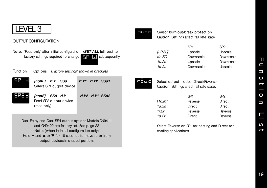
In addition to its technical capabilities, the Omega Engineering CN9400 is designed with user convenience in mind. The intuitive menu-driven interface allows for easy programming and operation. Users can quickly navigate through settings and parameters without extensive training, minimizing downtime and enhancing productivity.
Overall, the Omega Engineering CN9400 is a powerful and reliable temperature controller that combines advanced technology with user-friendly features. Its precision, durability, and connectivity make it an ideal choice for a wide range of industrial and research applications, ensuring accurate temperature management in even the most demanding environments.

