2.5Clock Selection
The DAQ-12 is equipped with a programmable clock circuit to produce data sampling rates independent from the clock rate of the host computer. An onboard 8254 programmable interval timer, with a 10 MHz clock input and either two or three cascaded 16-bit timers, provides the sampling rate. This enables the sampling rate to be adjusted from 5 us between samples to almost a year between samples, in as small as 100ns increments.
The DAQ-12's sampling rate can also be generated from an external clock input. This external clock can be connected directly to the A/D converter or through a 16-bit pre-divider, the multi-function timer. Samples are taken on the low to high transition of the clock.
WARNING: For the DAQ-12, the maximum data sampling rate is 5us. This restricts clock frequency to a maximum of 200 KHz. Sampling rates in excess of 200 KHz may result in erratic operation and unpredictable results.
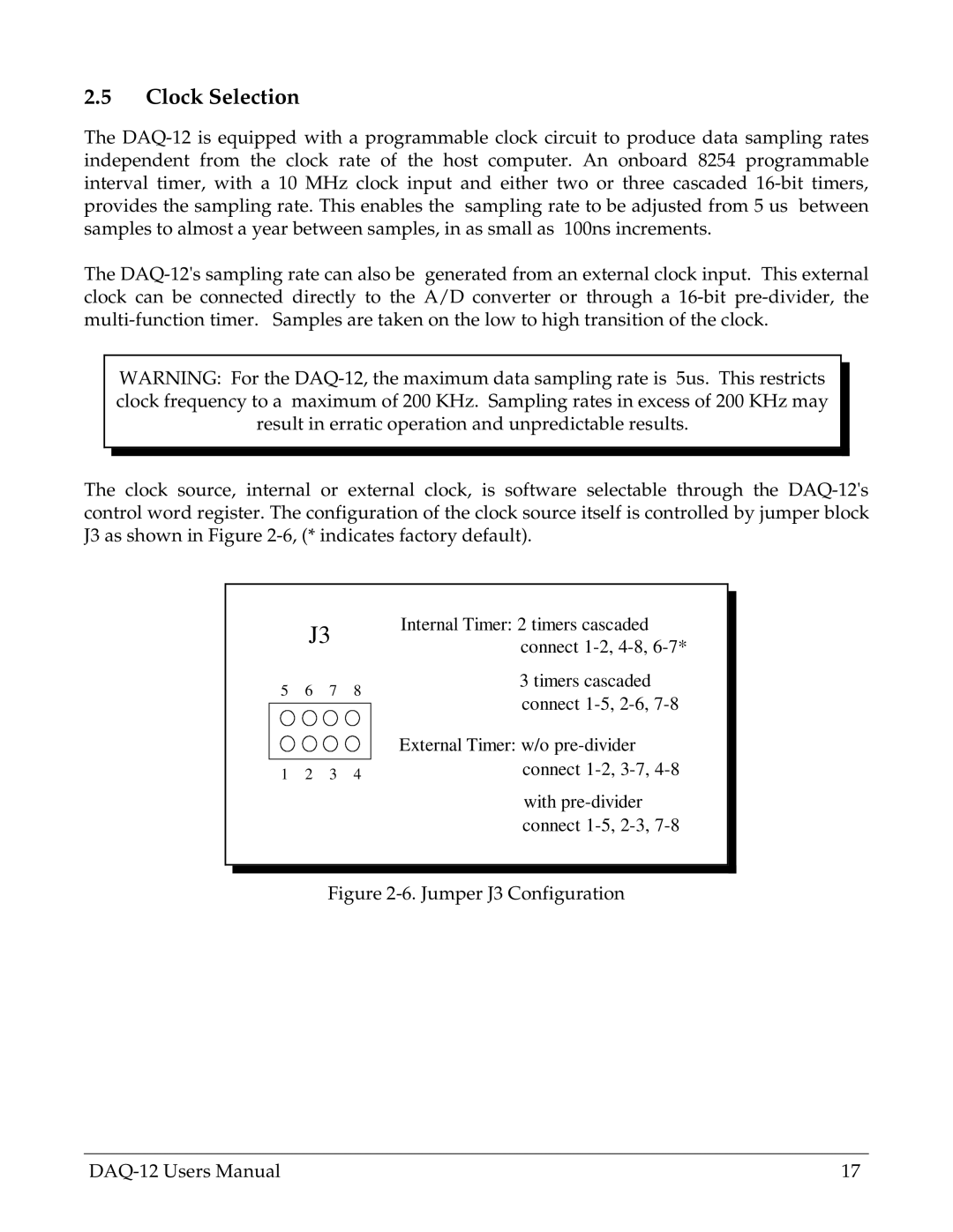
The clock source, internal or external clock, is software selectable through the DAQ-12's control word register. The configuration of the clock source itself is controlled by jumper block J3 as shown in Figure 2-6, (* indicates factory default).
Internal Timer: 2 timers cascaded connect 1-2, 4-8, 6-7*
3 timers cascaded connect 1-5, 2-6, 7-8
External Timer: w/o pre-divider connect 1-2, 3-7, 4-8
with pre-divider connect 1-5, 2-3, 7-8
Figure 2-6. Jumper J3 Configuration