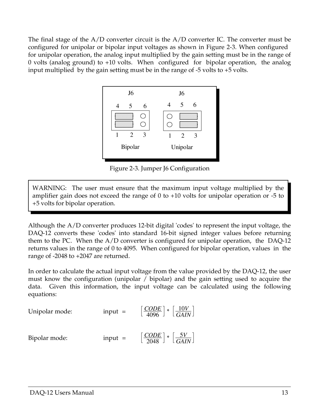
The final stage of the A/D converter circuit is the A/D converter IC. The converter must be configured for unipolar or bipolar input voltages as shown in Figure
J6
4 5 6
1 2 3
Bipolar
J6
4 5 6
1 2 3
Unipolar
Figure 2-3. Jumper J6 Configuration
WARNING: The user must ensure that the maximum input voltage multiplied by the amplifier gain does not exceed the range of 0 to +10 volts for unipolar operation or
Although the A/D converter produces 12-bit digital 'codes' to represent the input voltage, the DAQ-12 converts these 'codes' into standard 16-bit signed integer values before returning them to the PC. When the A/D converter is configured for unipolar operation, the DAQ-12 returns values in the range of 0 to 4095. When configured for bipolar operation, values in the range of -2048 to +2047 are returned.
In order to calculate the actual input voltage from the value provided by the DAQ-12, the user must know the configuration (unipolar / bipolar) and the gain setting used to acquire the data. Given this information, the input voltage can be calculated using the following equations:
Unipolar mode: | input = |
Bipolar mode: | input = |
CODE
4096
CODE
2048
*
*
10V
GAIN
5V
GAIN
13 |