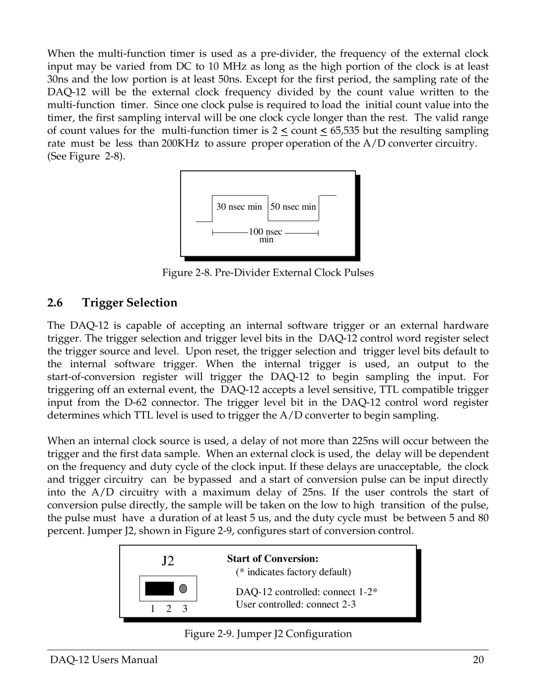
When the multi-function timer is used as a pre-divider, the frequency of the external clock input may be varied from DC to 10 MHz as long as the high portion of the clock is at least 30ns and the low portion is at least 50ns. Except for the first period, the sampling rate of the DAQ-12 will be the external clock frequency divided by the count value written to the multi-function timer. Since one clock pulse is required to load the initial count value into the timer, the first sampling interval will be one clock cycle longer than the rest. The valid range of count values for the multi-function timer is 2 < count < 65,535 but the resulting sampling rate must be less than 200KHz to assure proper operation of the A/D converter circuitry.
(See Figure 2-8).
30 nsec min 50 nsec min
100 nsec min
Figure 2-8. Pre-Divider External Clock Pulses
2.6Trigger Selection
The DAQ-12 is capable of accepting an internal software trigger or an external hardware trigger. The trigger selection and trigger level bits in the DAQ-12 control word register select the trigger source and level. Upon reset, the trigger selection and trigger level bits default to the internal software trigger. When the internal trigger is used, an output to the start-of-conversion register will trigger the DAQ-12 to begin sampling the input. For triggering off an external event, the DAQ-12 accepts a level sensitive, TTL compatible trigger input from the D-62 connector. The trigger level bit in the DAQ-12 control word register determines which TTL level is used to trigger the A/D converter to begin sampling.
When an internal clock source is used, a delay of not more than 225ns will occur between the trigger and the first data sample. When an external clock is used, the delay will be dependent on the frequency and duty cycle of the clock input. If these delays are unacceptable, the clock and trigger circuitry can be bypassed and a start of conversion pulse can be input directly into the A/D circuitry with a maximum delay of 25ns. If the user controls the start of conversion pulse directly, the sample will be taken on the low to high transition of the pulse, the pulse must have a duration of at least 5 us, and the duty cycle must be between 5 and 80 percent. Jumper J2, shown in Figure 2-9, configures start of conversion control.
| | | | | J2 | | Start of Conversion: | | |
| | | | | | | |
| | | | | | | | (* indicates factory default) | | |
| | | | | | | | DAQ-12 controlled: connect 1-2* | | |
| | | | | | | | | |
| | | | | | | | User controlled: connect 2-3 | | |
| 1 | 2 | | 3 | | |
| | | | |
| | | | | | | | | | |
| | | | | | | | | | |
| | | | | | | Figure 2-9. Jumper J2 Configuration |
| | | | |
DAQ-12 Users Manual | | | | 20 |