2. Circuit Board Description and Configuration
The base address of the DAQ-12 is selected using switches SW1 and SW2. The operating mode of the DAQ-12 is controlled by jumpers J1 through J7, while DMA and interrupt selections are set with jumpers J8 through J11. Connections to external equipment are made through the high density 62-pin connector CN1.
2.1Analog to Digital Converter
The analog to digital (A/D) section of the DAQ-12 accepts up to 8 differential or 16 single ended inputs from the D-62 connector. These inputs pass through a multiplexer circuit which selects the channel to be converted. The selected input is then amplified and presented to the A/D converter to be digitized. The digital output of the A/D is latched into a buffer to be read by the computer. The multiplexer circuit (MUX) selects one of the analog input channels to be input to the A/D converter. The typical characteristics of the multiplexer circuit are:
äswitching time: 0.5 us
settling time: 3.0 us
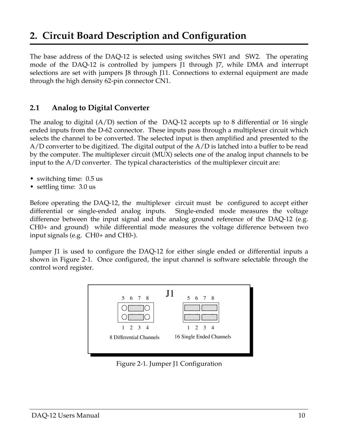
Before operating the DAQ-12, the multiplexer circuit must be configured to accept either differential or single-ended analog inputs. Single-ended mode measures the voltage difference between the input signal and the analog ground reference of the DAQ-12 (e.g. CH0+ and ground) while differential mode measures the voltage difference between two input signals (e.g. CH0+ and CH0-).
Jumper J1 is used to configure the DAQ-12 for either single ended or differential inputs a shown in Figure 2-1. Once configured, the input channel is software selectable through the control word register.
1 | 2 | 3 | 4 | 1 | 2 | 3 | 4 |
8 Differential Channels | 16 Single Ended Channels |
Figure 2-1. Jumper J1 Configuration