2.3Digital Input/Output
The DAQ-12 offers four bits of digital output and four bits of digital input for control/monitoring of external digital devices. The four digital output lines are LS TTL compatible and will initialize low (0 volts) on power-up. The four digital inputs are also LS TTL compatible. There is no termination provided on the digital input lines and a read of an unused digital input will result in an indeterminate value.
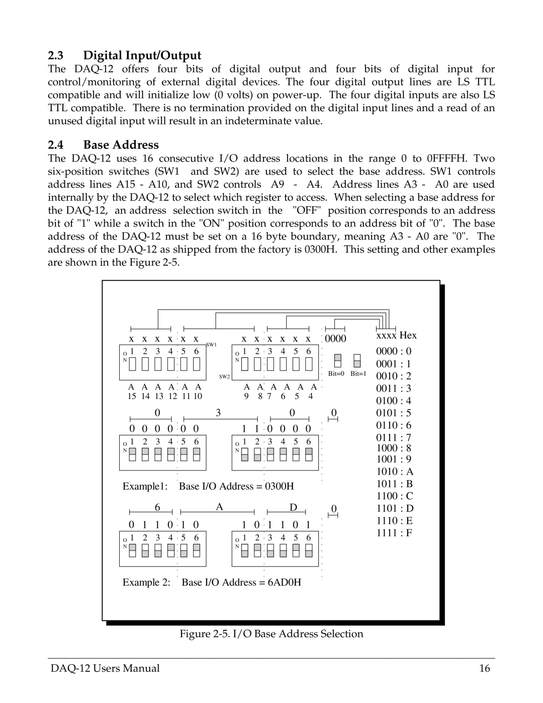
2.4Base Address
The DAQ-12 uses 16 consecutive I/O address locations in the range 0 to 0FFFFH. Two six-position switches (SW1 and SW2) are used to select the base address. SW1 controls address lines A15 - A10, and SW2 controls A9 - A4. Address lines A3 - A0 are used internally by the DAQ-12 to select which register to access. When selecting a base address for the DAQ-12, an address selection switch in the "OFF" position corresponds to an address bit of "1" while a switch in the "ON" position corresponds to an address bit of "0". The base address of the DAQ-12 must be set on a 16 byte boundary, meaning A3 - A0 are "0". The address of the DAQ-12 as shipped from the factory is 0300H. This setting and other examples are shown in the Figure 2-5.
A A A A A A 15 14 13 12 11 10
| | | | | | | | | | | | |
| | | | | | | | | | | | |
| | | | | | | | | | | | |
| | | | | | | | | | | | |
0000 | | xxxx | | Hex |
| | | | | | | |
| | | | | 0000 : 0 |
| Bit=0 Bit=1 | 0001 : 1 |
| 0010 : 2 |
| | | | |
| | | | | 0011 : 3 |
| | | | | 0100 : 4 |
O 1 2 3 4 5 6 | O 1 2 3 4 5 6 |
N | N |
Example1: | Base I/O Address = 0300H | | |
| | | | 6 | | | | | | | | A | | | | | | | D | | |
0 | 1 | 1 | 0 | 1 | 0 | | 1 | 0 | 1 | 1 | 0 | 1 |
O 1 2 | 3 | 4 | 5 6 | | O 1 | 2 | 3 4 | 5 6 |
N | | | | | | | | | | | N | | | | | | | | |
| | | | | | | | | | | | | | | | | | | | | |
00101 : 5
0110 : 6
0111 : 7
1000 : 8
1001 : 9
1010 : A
1011 : B
1100 : C
01101 : D
1110 : E
1111 : F
Example 2: Base I/O Address = 6AD0H
Figure 2-5. I/O Base Address Selection