VALID - when set, logic 1, indicates at least one data sample was lost because it was read by the personal computer before the next sample was converted. Data was lost because the sampling rate was too fast for the computer to acquire the data. VALID is reset by writing to the start conversion register.
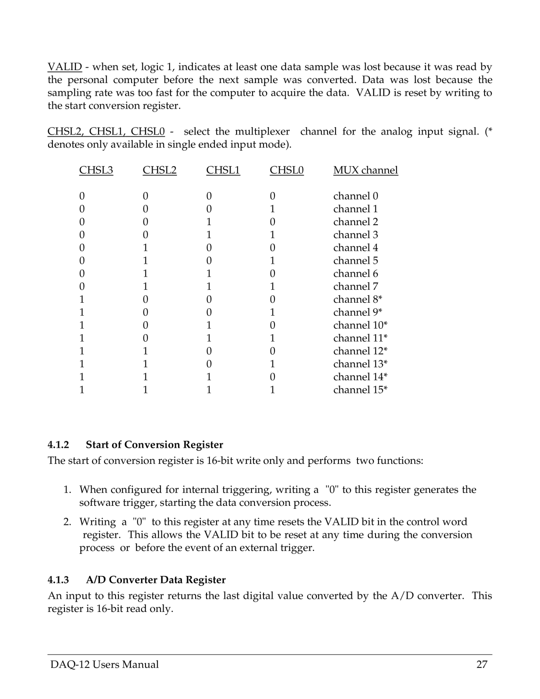
CHSL2, CHSL1, CHSL0 - select the multiplexer channel for the analog input signal. (* denotes only available in single ended input mode).
CHSL3 | CHSL2 | CHSL1 | CHSL0 | MUX channel |
0 | 0 | 0 | 0 | channel 0 |
0 | 0 | 0 | 1 | channel 1 |
0 | 0 | 1 | 0 | channel 2 |
0 | 0 | 1 | 1 | channel 3 |
0 | 1 | 0 | 0 | channel 4 |
0 | 1 | 0 | 1 | channel 5 |
0 | 1 | 1 | 0 | channel 6 |
0 | 1 | 1 | 1 | channel 7 |
1 | 0 | 0 | 0 | channel 8* |
1 | 0 | 0 | 1 | channel 9* |
1 | 0 | 1 | 0 | channel 10* |
1 | 0 | 1 | 1 | channel 11* |
1 | 1 | 0 | 0 | channel 12* |
1 | 1 | 0 | 1 | channel 13* |
1 | 1 | 1 | 0 | channel 14* |
1 | 1 | 1 | 1 | channel 15* |
4.1.2Start of Conversion Register
The start of conversion register is
1.When configured for internal triggering, writing a "0" to this register generates the software trigger, starting the data conversion process.
2.Writing a "0" to this register at any time resets the VALID bit in the control word register. This allows the VALID bit to be reset at any time during the conversion
process or before the event of an external trigger.
4.1.3A/D Converter Data Register
An input to this register returns the last digital value converted by the A/D converter. This register is
27 |