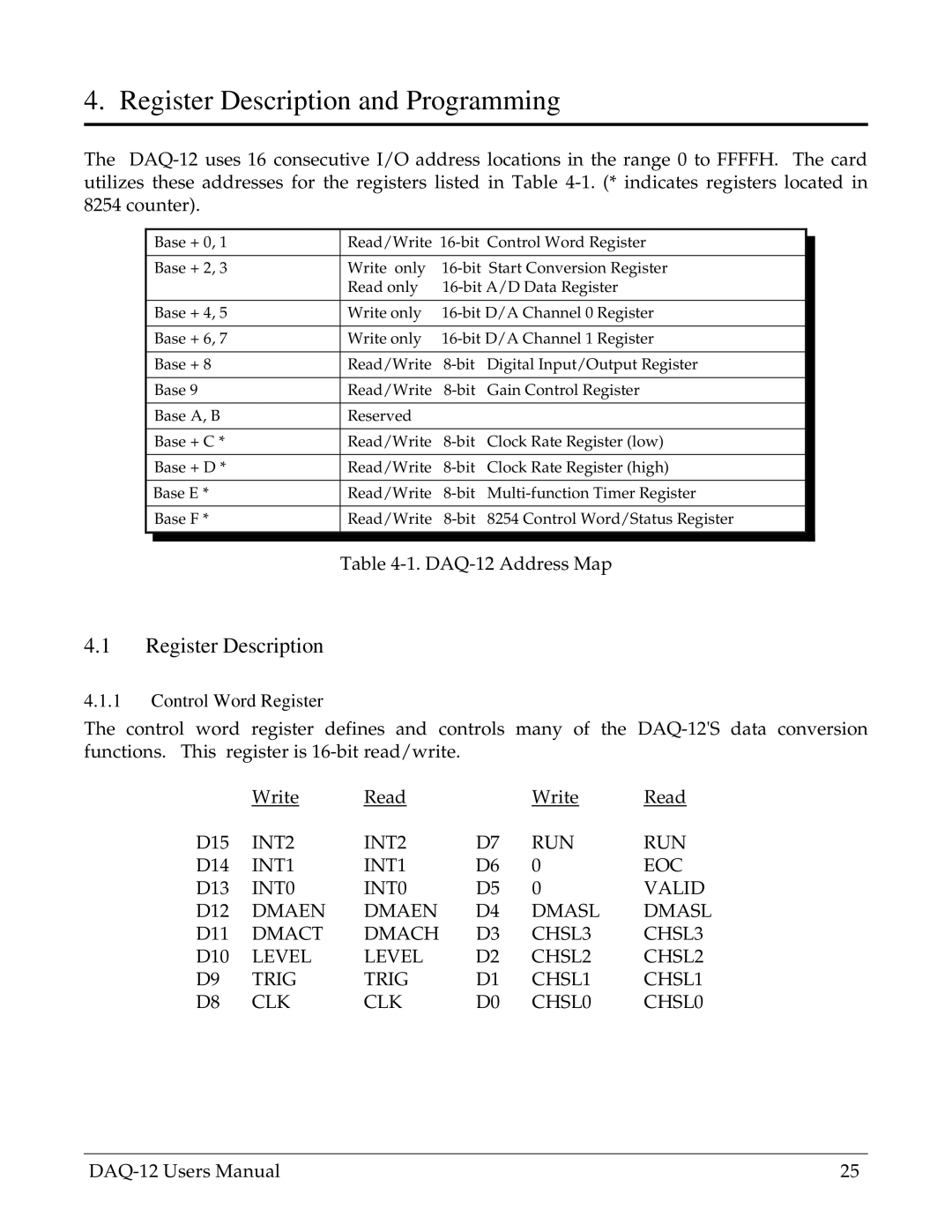
4. Register Description and Programming
The
| Base + 0, 1 | Read/Write |
| ||
|
| ||||
|
|
|
|
| |
| Base + 2, 3 | Write only |
| ||
|
| Read only |
| ||
|
|
|
|
| |
| Base + 4, 5 | Write only |
| ||
|
|
|
|
| |
| Base + 6, 7 | Write only |
| ||
|
|
|
|
|
|
| Base + 8 | Read/Write | Digital Input/Output Register |
| |
|
|
|
|
|
|
| Base 9 | Read/Write | Gain Control Register |
| |
|
|
|
|
|
|
| Base A, B | Reserved |
|
|
|
|
|
|
|
|
|
| Base + C * | Read/Write | Clock Rate Register (low) |
| |
|
|
|
|
|
|
| Base + D * | Read/Write | Clock Rate Register (high) |
| |
|
|
|
|
|
|
| Base E * | Read/Write |
| ||
|
|
|
|
|
|
| Base F * | Read/Write | 8254 Control Word/Status Register |
| |
|
|
|
|
|
|
|
|
|
|
|
|
Table
4.1Register Description
4.1.1Control Word Register
The control word register defines and controls many of the
| Write | Read |
| Write | Read |
D15 | INT2 | INT2 | D7 | RUN | RUN |
D14 | INT1 | INT1 | D6 | 0 | EOC |
D13 | INT0 | INT0 | D5 | 0 | VALID |
D12 | DMAEN | DMAEN | D4 | DMASL | DMASL |
D11 | DMACT | DMACH | D3 | CHSL3 | CHSL3 |
D10 | LEVEL | LEVEL | D2 | CHSL2 | CHSL2 |
D9 | TRIG | TRIG | D1 | CHSL1 | CHSL1 |
D8 | CLK | CLK | D0 | CHSL0 | CHSL0 |
25 |