2.2 Program Set Commands
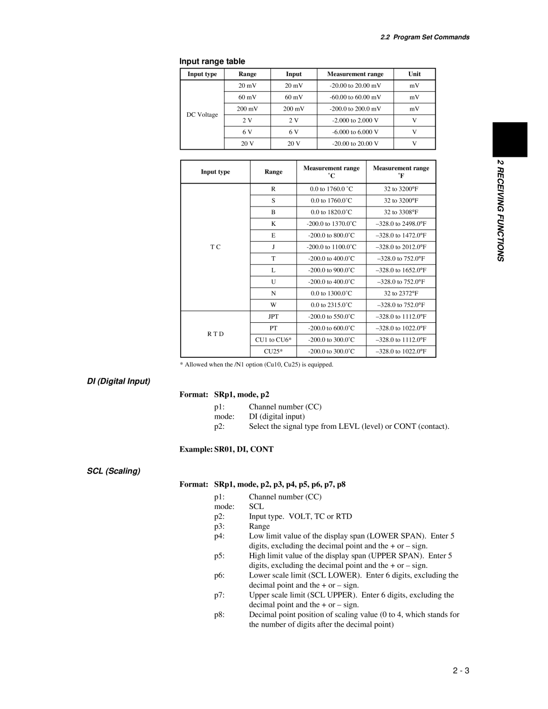
Input range table
Input type | Range | Input | Measurement range | Unit |
|
| |
|
|
|
|
|
|
|
|
|
| 20 mV | 20 mV | mV |
|
| |
|
|
|
|
|
|
|
|
|
| 60 mV | 60 mV | mV |
|
| |
|
|
|
|
|
|
|
|
DC Voltage |
| 200 mV | 200 mV | mV |
|
| |
|
|
|
|
|
|
| |
| 2 V | 2 V | V |
|
| ||
|
|
|
| ||||
|
|
|
|
|
|
|
|
|
| 6 V | 6 V | V |
|
| |
|
|
|
|
|
|
|
|
|
| 20 V | 20 V | V |
|
| |
|
|
|
|
|
|
|
|
|
|
|
|
|
|
|
|
|
| Measurement range | Measurement range | 2 | |
Input type | Range | RECEIVING | |||
˚C | ˚F | ||||
|
| ||||
|
|
|
| ||
| R | 0.0 to 1760.0 ˚C | 32 to 3200° F | ||
|
|
|
| ||
| S | 0.0 to 1760.0˚C | 32 to 3200° F | ||
|
|
|
| ||
| B | 0.0 to 1820.0˚C | 32 to 3308° F | ||
| FUNCTIONS | ||||
|
|
|
| ||
| K | ||||
|
|
|
| ||
| E | ||||
|
|
|
| ||
T C | J | ||||
|
|
|
| ||
| T | ||||
|
|
|
|
| |
| L |
| |||
|
|
|
|
| |
| U |
| |||
|
|
|
|
| |
| N | 0.0 to 1300.0˚C | 32 to 2372° F |
| |
|
|
|
|
| |
| W | 0.0 to 2315.0˚C |
| ||
|
|
|
|
| |
| JPT |
| |||
|
|
|
|
| |
R T D | PT |
| |||
|
|
|
| ||
CU1 to CU6* |
| ||||
|
| ||||
|
|
|
|
| |
| CU25* |
| |||
|
|
|
|
|
* Allowed when the /N1 option (Cu10, Cu25) is equipped.
DI (Digital Input)
Format: SRp1, mode, p2
p1: | Channel number (CC) |
mode: | DI (digital input) |
p2: | Select the signal type from LEVL (level) or CONT (contact). |
Example: SR01, DI, CONT
SCL (Scaling)
Format: SRp1, mode, p2, p3, p4, p5, p6, p7, p8
p1: | Channel number (CC) |
mode: | SCL |
p2: | Input type. VOLT, TC or RTD |
p3: | Range |
p4: | Low limit value of the display span (LOWER SPAN). Enter 5 |
| digits, excluding the decimal point and the + or – sign. |
p5: | High limit value of the display span (UPPER SPAN). Enter 5 |
| digits, excluding the decimal point and the + or – sign. |
p6: | Lower scale limit (SCL LOWER). Enter 6 digits, excluding the |
| decimal point and the + or – sign. |
p7: | Upper scale limit (SCL UPPER). Enter 6 digits, excluding the |
| decimal point and the + or – sign. |
p8: | Decimal point position of scaling value (0 to 4, which stands for |
| the number of digits after the decimal point) |
2 - 3