1.2 Interface Terminal
1.2.1Terminal Assignment
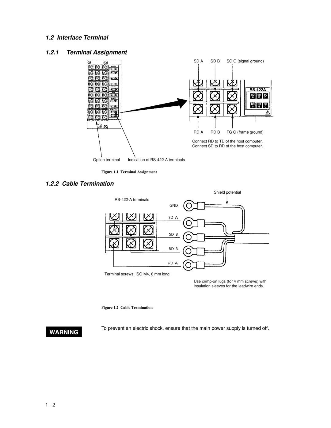
SD A SD B SG G (signal ground)
MEMORY
RD A RD B FG G (frame ground)
Connect RD to TD of the host computer.
Connect SD to RD of the host computer.
Option terminal | Indication of |
Figure 1.1 Terminal Assignment
1.2.2 Cable Termination
Shield potential
Terminal screws: ISO M4, 6 mm long
Use
Figure 1.2 Cable Termination
To prevent an electric shock, ensure that the main power supply is turned off.
1 - 2