1.3 Communication Wiring
1.3 Communication Wiring
If the host PC is equipped with an
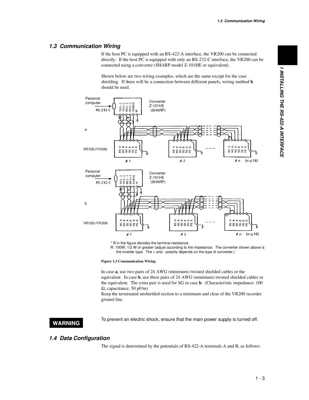
Shown below are two wiring examples, which are the same except for the case shielding. If there will be a connection between different panels, wiring method b should be used.
Personal
computerConverter
(SHARP)
R*
a
R*
Personal | Converter | |
computer | ||
| ||
| (SHARP) | |
| R* | |
b |
|
R*
* R in the figure denotes the terminal resistance.
R:100W, 1/2 W or greater (adjust according to the impedance. The converter shown above is the inverter type. The + and - polarity depends on the type of converter.)
Figure 1.3 Communication Wiring
In case a, use two pairs of 24 AWG (minimum) twisted shielded cables or the equivalent. In case b, use three pairs of 24 AWG (minimum) twisted shielded cables or the equivalent. The extra pair is used for SG in case b. (Characteristic impedance: 100
Ω, capacitance: 50 pF/m)
Keep the terminated unshielded section to a minimum and clear of the VR200 recorder ground line.
To prevent an electric shock, ensure that the main power supply is turned off.
1.4 Data Configuration
The signal is determined by the potentials of
1 INSTALLING THE
1 - 3