3.2 Output Data Formats
There are four formats in which data can be output.
•TS0 + ESC T + FM0 (outputs measured values in ASCII mode)
•TS0 + ESC T + FM1 (outputs measured values in Binary mode)
•TS1 + ESC T + LF (outputs parameter setting values)
•TS2 + ESC T + LF (outputs information on engineering unit and decimal point)
3.2.1Output Format of Measured Values in ASCII Mode
When the TS0, ESC T, and FM0 commands are received, the measured values and computed results are output as ASCII codes. When the ESC T command is received immediately after the TS0 command, the recorder transfers the internal data to the RS-
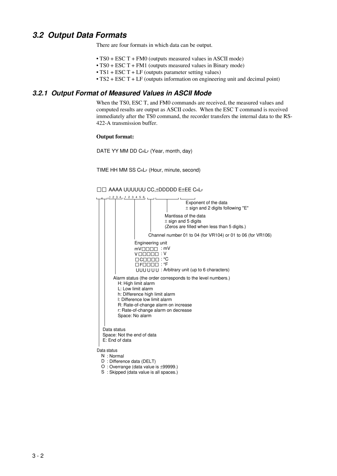
Output format:
DATE YY MM DD CRLF (Year, month, day)
TIME HH MM SS CRLF (Hour, minute, second)
AAAA UUUUUU CC,± DDDDD E± EE CRLF
1 2 3 4 1 2 3 4 5 6
Exponent of the data
± sign and 2 digits following "E"
Mantissa of the data
± sign and 5 digits
(Zeros are filled when less than 5 digits.)
Channel number 01 to 04 (for VR104) or 01 to 06 (for VR106)
Engineering unit
mV | : mV |
V | : V |
C | : ° C |
F | : ° F |
UUU U U U : Arbitrary unit (up to 6 characters)
Alarm status (the order corresponds to the level numbers.)
H:High limit alarm
L:Low limit alarm
h: Difference high limit alarm
l: Difference low limit alarm
R:
Data status
Space: Not the end of data
E: End of data
Data status
N : Normal
D : Difference data (DELT)
O: Overrange (data value is ± 99999.) S : Skipped (data value is all spaces.)
3 - 2