3Setting Up the Pump(s)
3.3Attaching the Pump
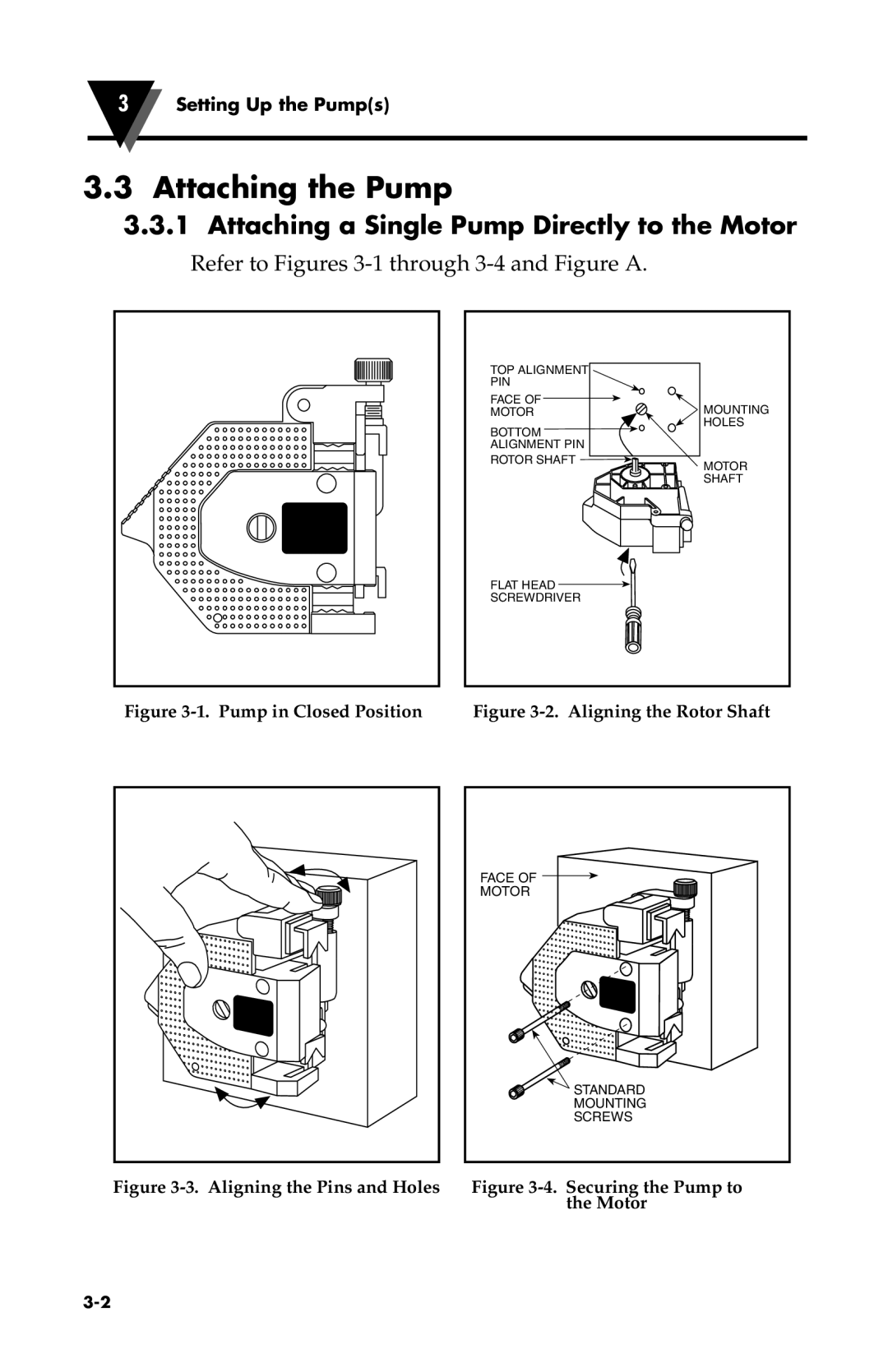
3.3.1Attaching a Single Pump Directly to the Motor
Refer to Figures 3-1 through 3-4 and Figure A.
TOP ALIGNMENT
PIN
FACE OF
MOTOR
BOTTOM ![]() ALIGNMENT PIN
ALIGNMENT PIN
ROTOR SHAFT ![]()
MOUNTING HOLES
MOTOR
SHAFT
FLAT HEAD
SCREWDRIVER
Figure | Figure |
FACE OF |
MOTOR |
STANDARD |
MOUNTING |
SCREWS |
Figure | Figure |
| the Motor |