The adapter plate is designed to have the same alignment pins and mounting holes as the front face of the standard pump motor. It acts as an interface between a non-standard pump motor and the peristaltic pump. The non-standard pump motor must have a motor shaft groove large enough to accept the the pump rotor shaft. It must also have at least two 8-32 mounting holes aligned with those on the adapter plate (refer to Figure 3-12).
Mounting the adapter plate to the motor (refer to Figure 3-8)
1.Align the plate so that the clearance holes fit over the alignment pins (on some units) of the non-standard motor.
2.Using the four 8-32 screws provided, attach the adapter plate to the motor.
Mounting the pump to the adapter plate
3.Make sure the pump is in the closed position. Refer to Figure 3-9.
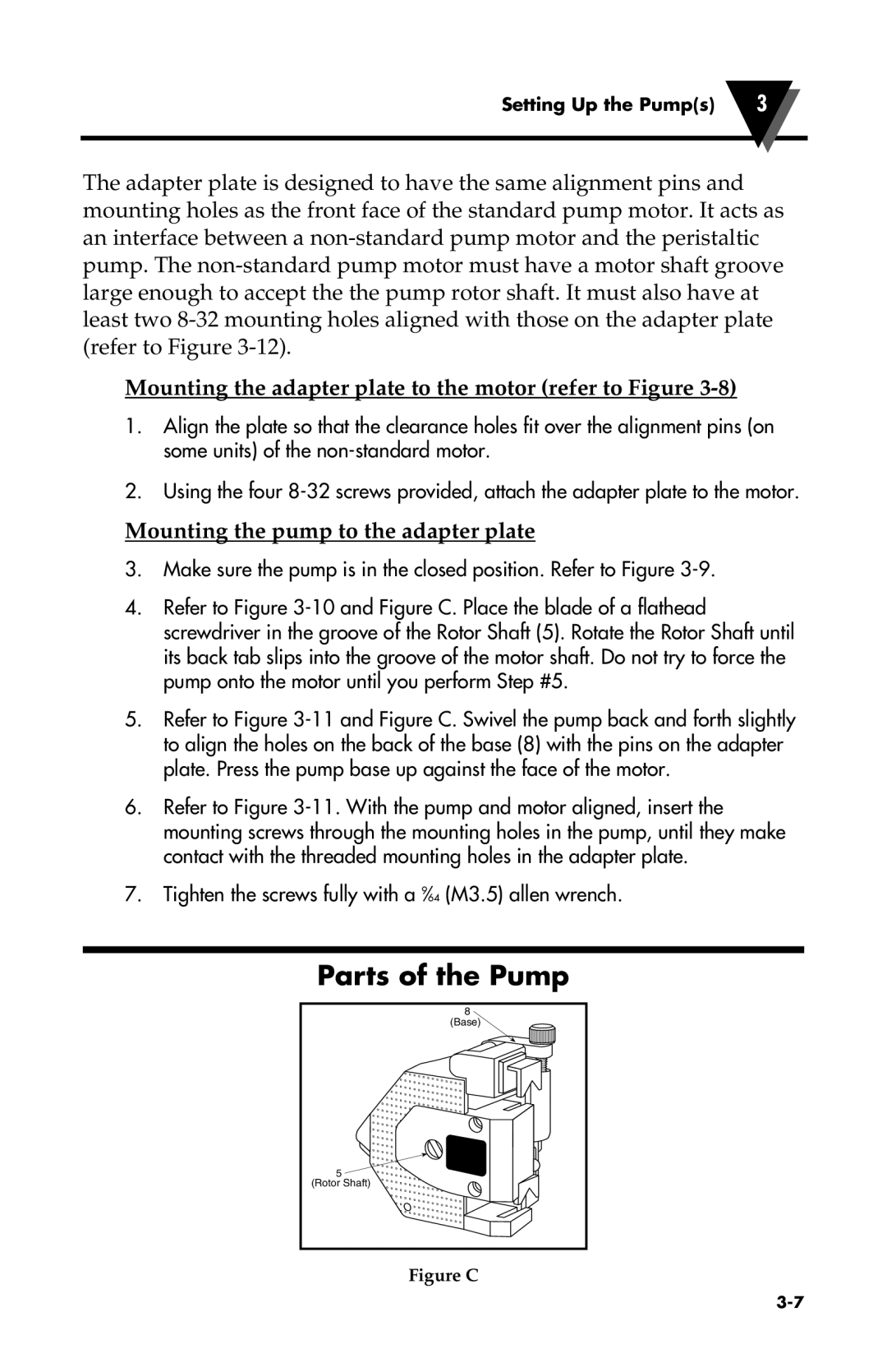
4.Refer to Figure 3-10 and Figure C. Place the blade of a flathead screwdriver in the groove of the Rotor Shaft (5). Rotate the Rotor Shaft until its back tab slips into the groove of the motor shaft. Do not try to force the pump onto the motor until you perform Step #5.
5.Refer to Figure 3-11 and Figure C. Swivel the pump back and forth slightly to align the holes on the back of the base (8) with the pins on the adapter plate. Press the pump base up against the face of the motor.
6.Refer to Figure 3-11. With the pump and motor aligned, insert the mounting screws through the mounting holes in the pump, until they make contact with the threaded mounting holes in the adapter plate.
7.Tighten the screws fully with a 9⁄64 (M3.5) allen wrench.
Parts of the Pump
8
(Base)
5 (Rotor Shaft)
Figure C